
What’s actually slowing this PC down?
Pick the symptom - the matching free tool is one click away.
iTechGuides is reader-supported. When you buy through links on our site, we may earn an affiliate commission. As an Amazon Associate I earn from qualifying purchases. Learn more
Neither predictive nor reactive control is universally better for robot-arm automation. A predictive controller such as model predictive control (MPC) can anticipate future motion, constraints, and disturbances when the robot model is accurate enough and the controller can finish its optimization inside a deterministic control cycle. A feedback-driven reactive controller can be the better fit when current sensor data is sufficient to correct the task and predictive optimization would add delay, integration work, or failure modes without a measurable benefit.
The decision belongs to the task and the implementation, not to the label. “Reactive” is a broad practical category rather than one standardized industrial-arm architecture, while “predictive” covers several methods; MPC is one concrete example. Compare the exact controller, robot, payload, sensing, timing budget, disturbances, commissioning effort, and validated cell-safety functions before choosing.
What exactly are you comparing: the robot arm or its control policy?
An industrial robot arm is the mechanical manipulator and its drive system. Predictive and reactive describe how a controller computes commands for that arm. The surrounding cell—vision, fixtures, conveyors, safety scanners, emergency stops, PLC logic, and operator interfaces—also affects the result. A change in policy does not by itself change the arm’s mechanical reach, payload, or safety rating.
Recommended Free Tools
The International Federation of Robotics (IFR), citing ISO 8373:2021, defines an industrial robot as an automatically controlled, reprogrammable, multipurpose manipulator programmable in three or more axes for industrial automation. That definition identifies the machine; it does not prescribe MPC, reactive feedback, artificial intelligence, or a particular sensor stack.
#1 Best Overall
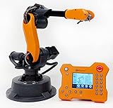
- WLKATA Mirobot Professional Kit. This Professional Kit includes everything in the Education Kit , plus a wireless Bluetooth controller.Part list:Robot arm,Power supply & High-speed USB cable & IDC cable, Pen holding, Micro servo gripper module,Pneumatic set, Multifunctional box,Mirobot Mecha sticker,Handbook,Wireless Bluetooth controller.
- Multiple control methods: computer terminal WLKATA Studio software control, APP mobile phone control, APP mobile phone control, three-dimensional virtual control (V-Rep Ros Matlab),Contains a matching robot controller for better and more comprehensive control
- WLkata Mirobot equipped with laser engraving, writing and drawing, handling and palletizing, mobile app control, etc. Multiple functions, reserved multiple expansion interfaces to support secondary development. Users can develop more application scenarios through software programming and hardware expansion to meet the needs of students of different ages.
- Desktop-level lightweight industrial robotic arm prototype, safe operation, comprehensive functions, freely set actions, add accessories arbitrarily, one arm has unlimited creativity!
- WLKATA is suitable for teaching and training scenarios, color sensor training, multi-fixture coordination training, joint training of six-axis robotic arms and code wheel robotic arms, scene training, painting and calligraphy art training, artificial intelligence voice training, etc.If you have any questions about installation or use, please check the manual or contact us, we will serve you wholeheartedly.
Use the two labels only after writing down the implementation being evaluated. “MPC on a six-axis arm with joint-state feedback and a vision-based disturbance estimate” is testable. “A predictive robot” is too vague to support a purchase or performance claim.
What does predictive control mean for a robot arm?
Predictive control uses a model of the robot or process to estimate how the system will evolve, optimizes commands over a finite future horizon, applies the next command (or short portion of the solution), then repeats the calculation with new state information. Model predictive control is the most useful concrete example for this comparison, but it is not a synonym for every predictive technique.
How an MPC cycle works
- Estimate the current state. The controller combines available measurements—such as joint position, velocity, and other application signals—into the state used by its model.
- Forecast a limited horizon. A dynamic model predicts future joint and task-space states for candidate control inputs.
- Optimize the inputs. The controller minimizes its chosen objective while observing limits such as joint ranges, velocity or torque bounds, path constraints, and synchronization requirements. The objective and constraints are application-specific.
- Apply the first part of the solution. Only the command needed for the next control interval is sent to the arm.
- Receding-horizon update. New measurements replace the old state estimate, and the optimization runs again. Forecasts therefore influence each instant without being trusted indefinitely.
This loop can anticipate a future collision constraint, a changing load, or a planned disturbance better than a controller that only corrects an error after it appears. The benefit depends on model fidelity, state-estimation quality, and whether the optimizer meets the arm’s timing deadline every cycle.
PC Slower Than It Used to Be?
A free scan shows the junk files, broken settings and background clutter dragging Windows down - then fixes them in one click.Free scan · Windows 10 & 11Crashes, No Sound, or Screen Glitches?
Random freezes, missing sound and display glitches usually trace back to one bad driver. Find and replace yours safely.Free scan · under a minuteWhy the model is the central trade-off
A complex arm model must represent enough of the mechanism, payload, friction, flexibility, and task interaction to make forecasts useful. Deriving and maintaining that model is difficult. The model can also become inaccurate when the payload, fixture, tool, or process changes. An optimizer that produces an elegant trajectory from a wrong model may be less useful than a simpler feedback loop that corrects measured error promptly.
A Control.com article dated August 10, 2020 identified model derivation and computational burden—the number of control variables and the resulting optimization work—as challenges for MPC. It also described industrial deployment under modeling uncertainty and external disturbance as limited at that time. Treat that as the article’s dated assessment, not as a current market-wide measurement.
What is reactive control for an industrial arm?
Reactive control responds to measured current conditions. A feedback loop compares the desired and observed state, then corrects the command; a higher-level policy can also use current force, proximity, or vision observations to select the next motion. The term covers many implementations, from conventional trajectory correction to sensor-driven behavior, so it should not be treated as one standardized architecture.
What the IFR examples show
The IFR describes robots using sensors and vision to respond to their external environment, including picking unsorted parts. In its robot-programming example, machine vision compares a weld part with a 3D model, detects deviations, and adapts the trajectory on the fly. That is a concrete example of sensed adaptation: the robot changes its path after observing variation. It does not prove that reactive control always beats MPC, that artificial intelligence is required, or that every vision system is reactive.
Free tools Windows power users keep installed
One-click scans. No signup required.
Reactive does not necessarily mean “model-free.” A feedback controller may use a kinematic model, feed-forward terms, filtering, or a state observer while still making decisions from the latest measurements rather than optimizing a long future horizon. Conversely, an MPC implementation can incorporate the same sensors. The distinction is the decision method and timing, not the presence or absence of a camera.
What is the practical difference between predictive and reactive control?
The following comparison is a decision framework, not a benchmark. The sources do not establish a universal speed, accuracy, reliability, or return-on-investment winner.
| Decision axis | Predictive/MPC considerations | Reactive/feedback considerations |
|---|---|---|
| Task and disturbances | Useful when future states, constraints, or anticipated disturbances materially affect the task; actual benefit depends on model fidelity. | May be sufficient when current measurements support timely correction and explicit forecasting adds little. |
| Model and computation | Requires a useful model and enough compute to optimize within the control cycle. | Avoids the specific MPC optimization burden, but still requires control computation, sensing, and timely response. |
| Timing and synchronization | Must fit deterministic timing requirements; sophistication does not excuse missed deadlines. | Must also meet response-time and multi-axis synchronization needs. |
| Adaptation and integration | Can combine sensing and optimization; integration complexity depends on the controller and application. | Sensor-driven adaptation can handle observed variation; sensing, calibration, and integration still matter. |
| Safety | No general safety superiority is established. Evaluate the complete cell and validated safety functions. | The same limitation applies; a reactive label is not a safety claim. |
When is predictive control the better engineering choice?
Predictive control deserves a serious evaluation when the next state matters before it is visible in the current error signal. That usually means the task has constraints, coupled axes, or disturbances that can be represented well enough for forecasts to improve decisions.
Rank #2
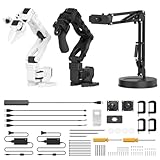
- 【End-to-End Imitation Learning】Hiwonder SO-ARM101 robot arm is an embodied intelligent hardware platform compatible with the Lerobot open-source framework. It provides developers with streamlined access to shared code, templates, and pre-trained models to explore the latest advancements in AI research.
- 【Dual-Camera Vision System】Equipped with both a gripper-mounted camera and an external camera, the system supports both precise manipulation and environmental awareness for accurate imitation learning.
- 【Hiwonder High-Performance Bus Servos】Featuring 12 high-torque bus servo motors with magnetic feedback, the Hiwonder SO-Arm101 robotic arm delivers smooth, stable motion, eliminating issues like power deficiency and jitter.
- 【Professional Control & Debugging】Integrated with the Hiwonder BusLinker V3.0 debugging board, the system supports servo scanning, real-time status monitoring, and trajectory control. The professional PC software simplifies device calibration and debugging, making it accessible for both researchers and hobbyists.
- 【Open-Source Compatibility】The SO-ARM101 robotic arm is designed to be fully compatible with the LeRobot open-source project. We acknowledge the contributions of the open-source community; all trademarks and copyrights belong to their respective owners.
Future constraints are important
If the arm must respect several limits simultaneously—such as a coordinated path, joint bounds, tool orientation, and an obstacle margin—an optimizer can consider those limits together over a horizon. This is different from correcting one measured error at a time. The expected advantage is conditional: the constraints must be represented accurately, and the solution must arrive before the arm needs it.
Disturbances can be anticipated
A conveyor timing signal, known payload change, or measured approach to a process limit can provide information about what is about to happen. A predictive controller can use that information to shape the next commands instead of waiting for a large tracking error. If the disturbance is unmeasured, highly irregular, or poorly represented by the model, the forecast may add little.
Multiple axes interact strongly
Six-axis arms require coordinated multi-axis motion. A controller that plans coupled inputs can be useful when changing one joint affects several task-space constraints. The benefit should be demonstrated on the intended arm and payload rather than assumed from the word “MPC.”
The project can support model and compute work
Predictive control brings model derivation, parameter identification, optimization software, state estimation, and monitoring into the project. It is a reasonable choice when the team can maintain those elements and has deterministic compute headroom. If the controller regularly overruns its cycle, a theoretically better plan cannot be applied safely or consistently.
When is reactive control the better engineering choice?
Reactive feedback is often the sensible baseline when current measurements already contain the information needed to correct the task and the process does not benefit from an explicit future optimization.
The Tool Desk
Outbyte PC Repair FREERepair Windows errors before they cause bigger problemsFix Now →Outbyte Driver Updater FREEFix the driver behind crashes, sound loss and screen glitchesFind Drivers →Observed variation dominates
For parts that arrive with changing position or orientation, a calibrated vision or force signal can drive a correction as soon as the deviation is observed. The IFR welding example illustrates this pattern. The engineering question is whether that correction is timely and repeatable, not whether the system is marketed as intelligent.
The model would be fragile
When payloads, fixtures, contact conditions, or materials change frequently, maintaining a detailed dynamic model may cost more than it returns. A feedback loop can still require calibration and filtering, but it does not incur the specific MPC optimization burden.
The control cycle is tight
A simple controller may leave more deterministic compute margin for the arm’s servo loop and for safety-related functions. This is not automatic: sensing, filtering, inverse kinematics, and communications can also consume time. Measure the complete implementation.
Commissioning and maintenance favor transparency
Teams may prefer a control path whose corrections can be traced directly to a measured error. That can simplify fault finding and parameter changes, provided the sensor calibration, synchronization, and limits are documented. A reactive design is not maintenance-free; it still needs reliable measurements and integration with the robot controller.
Do these 3 things before closing this tab:
1Fix the driver behind crashes, sound loss and screen glitches2Repair Windows errors before they cause bigger problems3Scan for outdated or missing drivers - takes under a minuteHow do timing and multi-axis synchronization change the decision?
Timing is a hard design constraint for both approaches. A high-performance robot arm must coordinate commands across its axes at deterministic intervals. A Control.com white paper on robot control explains that delays or jitter can compromise synchronization and performance. An MPC solver that occasionally misses its deadline is not equivalent to the same solver meeting every deadline.
Rank #3
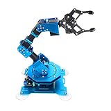
- Spark Your Creativity with Robotic Arm: Hiwonder-xArm1S is a high-quality desktop robot arm capable of remote-control grasping, object transportation, custom actions, graphical programming, and more. It serves as the ideal platform for building and showcasing creative projects and for learning about bionic robotics.
- Intelligent Servo: Hiwonder-xArm1S is equipped with 6 high-precision intelligent serial bus servos that provide position, voltage and temperature feedback. These powerful servos deliver strong torque, enabling the robot arm to grasp objects weighing up to 500g with ease.
- Premium Structure Design: The robot arm is constructed from an exquisite aluminum alloy bracket. The base is fortified with high-torque servos and industrial-grade bearings, guaranteeing exceptional stability.
- Various Control Methods: It supports PC, phone app, mouse, wireless PS2 Wireless Controller, and you can also control the robotic at your fingertips. With these control methods, xArm robotic Arm would bring more methods of play and study, perfect for realizing your innovative programming ideas and coding study.
- Versatile Action Editing: Hiwonder-xArm1S provides various action editing methods through a easy-to-use interface, including PC, app, and offline manual editing. This versatility allows you to easily create a wide range of robot applications.
Define the real-time budget before selecting an algorithm
- Identify the servo and supervisory control-cycle periods specified by the arm/controller documentation.
- Reserve time for state acquisition, filtering, kinematics, optimization or feedback computation, communications, logging, and fault handling.
- Measure worst-case execution time and deadline misses, not only average CPU load.
- Check that commands for all relevant axes are time-aligned and that network or middleware jitter does not break the assumed loop.
The same checks apply to a reactive system. Fast feedback cannot compensate for a camera pipeline, network link, or actuator command that arrives too late. Determinism should be treated as a pass/fail requirement before comparing higher-level performance.
Does adding vision or AI make an arm reactive?
No. Vision is a measurement source, and AI is one possible way to interpret measurements. A vision-guided trajectory correction can be reactive if it uses the current observation to choose the next command; an MPC can also use vision-derived state or disturbance estimates. The control architecture is defined by how commands are computed and updated.
The IFR’s “Sense and Respond” examples show why sensing is valuable: a robot can observe unsorted parts or deviations from a 3D model and adapt. The same IFR material notes ROS-Industrial work aimed at code reusability while highlighting strict real-time requirements, functional safety, and liability concerns in industrial applications. Those are integration considerations, not proof that a particular middleware, AI model, or controller is suitable for every cell.
Quick wins for a faster PC:
Clear out junk files and repair common Windows errorsFree Scan →Fix the driver behind crashes, sound loss and screen glitchesFind Drivers →Is predictive control safer than reactive control?
Neither label provides a general safety advantage. Safety depends on the complete cell design, the hazards identified in a task-specific risk assessment, and safety functions that have been implemented and validated for the selected hardware and software.
A predictive planner may account for a modeled obstacle, but an inaccurate model does not replace a validated protective function. A reactive system may stop or alter motion after a sensor event, but detection latency, sensor coverage, and failure handling determine whether that response is adequate. Keep safety-rated monitoring, emergency-stop behavior, protective separation, speed and force limits, and restart procedures separate from claims about optimization quality.
Do not infer compliance, a safety category, or a performance level from an algorithm name. Confirm the applicable requirements with the arm supplier, integrator, and safety assessor for the actual cell.
How should you choose between the two approaches?
Use a staged engineering process rather than selecting a label first.
- Describe the task and cell. Record the arm model, tool, payload range, workspace, cycle sequence, fixtures, conveyors, part variation, contact conditions, and operator access.
- Identify the exact control loop. Name the controller, policy, state estimator, sensors, command interface, and update rate. State whether the candidate predictive method is MPC or another technique.
- List disturbances and constraints. Separate predictable changes from surprises. Document collision margins, joint limits, synchronization needs, process tolerances, and recovery states.
- Set timing requirements. Obtain the documented control-cycle deadlines, then measure acquisition, computation, communication, and actuation latency under worst-case load.
- Assess model viability. Determine which parameters must be identified, how payload and fixture changes affect them, and how model mismatch will be detected and handled.
- Build a representative test. Use the intended arm, tool, payload, sensing, controller hardware, and realistic disturbances. A simulation-only result does not establish production performance.
- Measure task outcomes. Record cycle time, tracking error, path or process quality, deadline misses, recovery behavior, calibration sensitivity, and operator interventions. Do not substitute unrelated published figures for these measurements.
- Estimate integration effort. Include model development, sensor calibration, controller interfaces, software validation, diagnostics, training, and future changeovers.
- Validate safety separately. Complete the cell risk assessment and validate every required safety function with the chosen architecture.
- Choose the simplest method that meets the acceptance criteria. Add predictive optimization only when the measured benefit justifies its model, compute, and maintenance burden.
How can you run a fair predictive-versus-reactive test?
A fair comparison changes the control policy while holding the physical setup and acceptance criteria constant. Use the same arm, payload, tool, calibration, sensor placement, command interface, and safety limits. If one method receives a future disturbance signal that the other cannot access, document that difference rather than presenting the result as an architecture-only comparison.
Include normal and adverse cases
- Nominal parts and the full documented range of position, orientation, and payload variation.
- Representative sensor noise, missing observations, and calibration drift.
- Expected external disturbances and a controlled set of model-mismatch cases.
- Startup, stop, resume, fault, and recovery sequences.
- Peak computational load and communication congestion likely in production.
Report measurements with conditions
Record the hardware and software versions, control-cycle settings, payload, fixture, sensor configuration, test date, and disturbance used for each result. Report distributions and failure modes rather than a single best run. The reviewed sources contain no controlled, model-specific benchmark that establishes a winner, so any numerical advantage must come from your own validated test or a clearly identified external study.
Independent reader supportYour contribution helps us test, update, and keep practical guides available for everyone.What commonly goes wrong, and how do you recover?
The predictive model is wrong
Symptom: tracking degrades after a tool or payload change, or the optimizer repeatedly chooses commands that disagree with measured motion. Response: verify payload and inertia data, recalibrate the state and tool frames, compare predicted and measured trajectories, and define a fallback or degraded mode. Do not silently widen limits to hide model error.
Rank #4

- Synria Alicia-M is a lightweight 6-axis robotic arm designed for embodied AI research, robotics laboratories, teleoperation, imitation learning, and light industrial automation. It supports advanced manipulation workflows for VLA, ACT, and Diffusion Policy applications.
- With a 750mm working space and 1.5kg continuous effective payload, Alicia-M provides a larger operating range for object handling, testing, teaching, and automation tasks while maintaining a compact desktop-friendly structure.
- Built with precision motion control, Alicia-M offers ±0.1mm repeatability to support reliable task execution, experimental consistency, and long-term robotic operation in research, education, and engineering environments.
- Supports ROS2 teleoperation, gravity compensation, velocity mode, and MIT force control mode, enabling smoother manual guidance, responsive control, and safer interaction during data collection, task demonstration, and robotic learning.
- The full machine weighs approximately 5.1kg and uses DC24V power with CAN communication, making it easier to deploy in labs, classrooms, R&D workstations, and light industrial scenarios. Compatible with open-source robotics workflows and simulation-first control development.
The optimizer misses deadlines
Symptom: variable latency, stale commands, or multi-axis jitter appears under peak load. Response: profile worst-case execution time, reduce unnecessary decision variables or horizon length only after checking task impact, move non-real-time work out of the control path, and enforce a defined behavior when a solution is late. If the deadline still cannot be guaranteed, use a controller that fits the budget.
Reactive corrections oscillate
Symptom: the arm hunts around a target or amplifies noisy measurements. Response: inspect sensor latency and calibration, tune gains and filtering within the documented limits, verify coordinate frames, and test the response with the real payload. A faster loop is not automatically a better loop if its measurements are delayed or noisy.
Vision sees the part but the arm misses it
Symptom: detections look correct while the tool path is offset. Response: check camera-to-robot calibration, timing between image capture and motion, part-fixture assumptions, and whether the correction is applied in the correct frame. Confirm the result with a known reference before changing the control policy.
Middleware integration breaks real-time behavior
Symptom: a reusable software component works in a demonstration but introduces jitter or unbounded queues in production. Response: separate supervisory and servo-critical paths, measure end-to-end latency, define queue and timeout behavior, and review functional-safety and liability requirements with the integrator. ROS-Industrial discussions cited by the IFR specifically call out strict real-time and safety concerns.
Safety is treated as an algorithm feature
Symptom: a team assumes that prediction or fast reaction alone proves a safe cell. Response: return to the task-specific risk assessment, verify safety-rated functions and fault responses, and document validation evidence independently of performance tests.
What should be in a procurement and commissioning specification?
Write requirements that a supplier or integrator can demonstrate on the intended cell:
- The exact arm, controller, firmware, tool, payload range, and supported command interfaces.
- The control policy name and location in the architecture, including whether it is MPC, feedback trajectory correction, or a hybrid.
- Sensor types, calibration procedure, timestamping, field of view, and behavior when measurements are unavailable.
- Required control-cycle period, worst-case latency, synchronization tolerance, and deadline-miss handling.
- Model parameters, identification procedure, change-control process, and acceptance tests for new payloads or fixtures.
- Test disturbances, variability range, cycle-time and tracking-error metrics, recovery cases, and reporting format.
- Integration boundaries for PLC, vision, middleware, logging, diagnostics, and software updates.
- Safety requirements, validation responsibilities, operating modes, and documented limits for the complete cell.
During commissioning, keep a record of calibration values, software versions, parameter changes, measured timing, test results, unresolved deviations, and the conditions under which the acceptance results were obtained. This record makes later troubleshooting possible and prevents a one-time demonstration from becoming an unsupported production claim.
What is the defensible bottom line for automation teams?
Choose predictive control when a validated model, future constraints, and anticipated disturbances create a measurable need for horizon-based optimization—and when the computation can meet deterministic deadlines. Choose reactive feedback when current measurements provide timely corrections and the additional model and optimization burden does not improve the acceptance metrics. In both cases, validate the implementation on the intended arm and payload, and assess safety at the cell level.
Frequently Asked Questions
Can a reactive robot controller still use a mathematical model?
Yes. Feedback control can use kinematics, feed-forward terms, filtering, or a state observer while still reacting to the latest measurements. The useful distinction is whether the policy relies on repeated future-horizon optimization, not whether any model appears in the software.
Does MPC require a full digital twin of the robot cell?
No. MPC requires a model adequate for the states, inputs, and constraints it is optimizing; that model may be narrower than a complete digital twin. The required fidelity depends on the task, payload changes, and disturbances that the controller must predict.
Can predictive and reactive methods be combined in one arm?
They can occupy different layers or operate together: an optimizer can generate a reference while a fast feedback loop corrects measured tracking error. The combined design still has to meet the same timing, synchronization, integration, and safety validation requirements as either method alone.
What evidence should a vendor provide before an automation purchase?
Ask for a demonstration on the specified arm, tool, payload, sensors, and controller hardware, with worst-case timing and representative disturbances recorded. Require the test conditions, deadline-miss behavior, calibration assumptions, recovery sequences, and safety-validation responsibilities in writing rather than accepting an untethered performance claim.
Quick Recap
Product prices and availability are accurate as of the date/time indicated and are subject to change. Any price and availability information displayed on Amazon at the time of purchase will apply.
Quick wins for a faster PC:
Fix the driver behind crashes, sound loss and screen glitchesFind Drivers →Repair Windows errors before they cause bigger problemsFix Now →Scan for outdated or missing drivers - takes under a minuteDriver Scan →
