
Do these 3 things before closing this tab:
1Fix the driver behind crashes, sound loss and screen glitches2Repair Windows errors before they cause bigger problems3Scan for outdated or missing drivers - takes under a minuteA second-order IIR filter, commonly called a biquad, implements a pair of poles and up to a pair of zeros. To build a higher-order filter, cascade biquads—and, for an odd-order filter, one first-order section—rather than relying on one long recursive equation. The practical path is to choose a prototype, calculate its digital coefficients, factor the result into real-coefficient sections, scale each section, and verify that every pole remains inside the unit circle using the coefficients at the precision your implementation will actually use.
Part 1: What a biquad computes
Transfer function and sample-by-sample equation
Using the Texas Instruments convention, a biquad has the transfer function:
H(z) = (b0 + b1 z^-1 + b2 z^-2) / (1 + a1 z^-1 + a2 z^-2)
Its corresponding sample-domain recurrence is:
y[n] = b0x[n] + b1x[n-1] + b2x[n-2] - a1y[n-1] - a2y[n-2]
The Tool Desk
Outbyte PC Repair FREERepair Windows errors before they cause bigger problemsFix Now →Outbyte Driver Updater FREEFix the driver behind crashes, sound loss and screen glitchesFind Drivers →#1 Best Overall

- Advanced ADAU1467 DSP core for superior processing capabilities.
- Compact design suitable for embedded systems and applications.
- Supports various formats and provides sound output.
- Ideal for developers and engineers seeking to enhance projects.
- Easy integration with existing systems and various devices.
The feedforward coefficients b0, b1, and b2 weight the current and two previous input samples. The feedback coefficients a1 and a2 weight the two previous output samples. Because the denominator is written with plus signs, its terms appear subtracted in this recurrence.
Match the coefficient signs to the implementation
Coefficient conventions differ across design tools and APIs. Some express the denominator with plus signs and subtract feedback terms in the recurrence; others store already-negated feedback coefficients and add them. These are alternative representations of the same filter, not different filter behavior. Before copying coefficients into code or a library, check the documented transfer function or recurrence and convert the signs if needed. A sign mismatch changes the poles and therefore the filter.
Rank #2

- Complete ADAU1401 Single-Chip Module: Built around the ADAU1401 with embedded 28 / 56-bit processing, analog-to-digital and digital-to-analog conversion, microcontroller-style control interfaces — all on compact board for quick prototyping
- Self-Booting from Onboard Storage: The module loads its program independently from onboard non-volatile storage at power-up and can save current parameters back to storage on shutdown, eliminating the need for an external main controller in standalone setups
- Expandable via I2C and 4-Wire Ports: All function ports are out, including digital I2S input / output, push-button inputs, drive, auxiliary analog inputs for volume controls, and rotary — letting users extend the board as needed
- 98.5 Dynamic Range for Clear Sound Output: Two analog input channels and four output channels deliver 98.5 of analog-to-analog dynamic range, with digital input and output ports for linking additional conversion in the chain
- Stable Across Wide Temperature Range: for a working span from minus 40 to 105 degrees Celsius, this board suits both casual desktop use and more demanding environments where temperature stability is important
Part 2: Choose a prototype and obtain digital coefficients
Start from the response you need
Common analog prototypes include Butterworth, Chebyshev, elliptic, and Bessel designs. They make different response trade-offs, so select one according to the desired frequency response rather than treating the names as interchangeable. Analog Devices describes a design process that begins with an analog transfer function H(s) and transforms it into a digital transfer function H(z). The resulting digital coefficients depend on the chosen prototype and transformation; there is no one coefficient set that represents every low-pass, high-pass, band-pass, or other filter.
Keep the design and implementation conventions aligned
After the analog-to-digital transformation, express the result using the same coefficient convention as the target implementation. If the design produces an overall filter of order greater than two, factor its transfer function into second-order sections (SOS). For an odd order, include a first-order remainder. This gives the implementation a sequence of manageable recursive sections instead of one high-order recurrence.
Rank #3
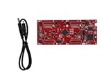
- DEVELOPMENT PLATFORM: Texas Instruments C2000 MCU F280025C LaunchPad development kit for rapid prototyping and evaluation
- CONNECTIVITY: Features USB connection cable for programming, debugging, and power supply
- PROCESSOR: Built around the F280025C microcontroller, ideal for real-time control applications and digital signal processing
- DESIGN FEATURES: Red PCB board with comprehensive development capabilities and expansion headers for additional functionality
- COMPATIBILITY: Supports TI's development ecosystem with Code Composer Studio and other programming tools
Part 3: Factor a high-order filter into cascaded sections
Pair poles and zeros into real-coefficient sections
A real-coefficient transfer function may have complex poles or zeros, which occur in conjugate pairs. Pair each complex root with its conjugate to form a second-order section with real coefficients. Real roots can also be paired into second-order sections; if an odd-order filter leaves one root unpaired, implement that factor as a first-order section. The final cascade reproduces the factored transfer function when the section responses are multiplied together.
Texas Instruments describes retaining scale information in a section’s numerator, including b0, while forming the sections. In practice, distribute the total gain across sections deliberately: a very large or very small gain in a single section can create avoidable internal-level problems even when the cascade’s overall response is correct.
Rank #4

- Fully programmable ADAU1467 DSP core board with 32-bit and 64-bit processing capabilities, ideal for multimedia and applications.
- User-friendly SigmaStudio software allows for drag-and-drop system creation without coding, enabling easy development of custom processing systems.
- Supports various applications including digital frequency dividers, mixers, and equalizers, making it perfect for professional setups.
- Includes multiple interfaces such as , SPI, and IIC for seamless integration and real-time tuning, ensuring optimal performance in any project.
- Comes with comprehensive documentation including schematics, PCB size charts, and application routines to facilitate easy implementation and .
Why cascade instead of using one high-order recurrence?
Several biquads are generally less sensitive to coefficient quantization and recursive round-off than a single direct-form implementation of the same high-order filter. The advantage is not that quantization disappears: each section still uses finite-precision coefficients and arithmetic. Cascading makes the numerical behavior easier to manage section by section, while scaling helps prevent internal values from exceeding the available range or becoming unnecessarily small.
Part 4: Choose a realization and account for finite precision
Direct form I and direct form II
Direct form I (DF1) and direct form II (DF2) implement the same second-order equation but organize their stored state differently. Analog Devices describes DF1 as using four registers and DF2 as an equivalent implementation with two delay elements. These are structural counts, not a promise of a particular processor’s speed or total memory use; the best choice depends on the implementation and its numeric format.
Free tools Windows power users keep installed
One-click scans. No signup required.
Best Value

- Multi-Channel Signal Acquisition Based on ADS1299 for high-resolution raw signal data collection and analysis.
- WiFi UART Wireless Communication Supports stable wireless serial data transmission for development and testing.
- Complete Development Resources Includes SDK package, communication protocol, and PC software source code.
- Open Hardware Design Provides schematic files and supports secondary development and customization.
- STM32 Development Kit Supports rapid integration with STM32 platforms and embedded applications.
| Realization | State storage described in the source | Practical consideration |
|---|---|---|
| Direct form I | Four registers (Analog Devices) | Separates input and output history; confirm that the API’s coefficient signs and state layout match the recurrence you use. |
| Direct form II | Two delay elements (Analog Devices) | Uses fewer delay elements structurally, but the internal state levels still need suitable scaling and numeric range. |
Neither form is universally superior. Intel IPP documents DF2 as its default biquad representation unless a DF1 suffix is selected; that is a library choice, not proof that DF2 is always faster, more accurate, or preferable in another environment.
Check stability after coefficient quantization
For the denominator convention used above, the poles are the roots of z^2 + a1z + a2 = 0. A discrete-time IIR section is stable only if every pole lies strictly inside the unit circle in the z-plane. Check the poles after the coefficients have been rounded or otherwise represented at the target implementation’s precision—not only from higher-precision design coefficients. Quantization can move poles, so a design that is stable before conversion is not sufficient evidence that the implemented section remains stable.
- Use the exact quantized feedback coefficients that the running implementation will use.
- Recompute the denominator roots for every section.
- Confirm that each pole has magnitude less than one.
- Run signal-level tests as an additional check; they do not replace the pole test.
Part 5: Scale, initialize, and verify the cascade
Set section gains and check internal levels
Section scaling controls the signal level passed between biquads and the levels within each section’s recursive state. Choose gains so intermediate values fit the target numeric range with adequate headroom. Check internal section levels under the signals and operating conditions that matter for your application; a cascade can have a reasonable overall response and still produce an inconveniently large intermediate value. The cited sources do not establish a universal section order or scaling rule for every filter and implementation.
Initialize and preserve state between blocks
A biquad is stateful: its next output depends on stored input and output history (or the corresponding DF2 delay state). Initialize that state explicitly, then preserve it when processing consecutive audio blocks. Resetting the delay state at every block boundary makes the filter behave as though each block were a new signal and can create discontinuities. Intel IPP’s documented workflow includes initialization, block processing, and delay-line get/set operations. Apple Accelerate also exposes stateful biquad processing and delay-line management; use the API documentation for the particular interface you are calling to confirm its exact state layout and initialization requirements.
Crashes, No Sound, or Screen Glitches?
Random freezes, missing sound and display glitches usually trace back to one bad driver. Find and replace yours safely.Free scan · under a minuteWindows Errors? Fix Them Before They Spread
Repair common Windows errors and clear accumulated junk for a smoother, more stable PC - no reinstall needed.Free scan · no reinstallQuick Recap
Implementation checklist
- Design: choose a suitable prototype and transform its
H(s)into a digitalH(z). - Factor: express the result as real-coefficient SOS sections, with a first-order remainder if the overall order is odd.
- Convert: map coefficients to the target API’s sign and storage convention.
- Scale: distribute gain and check intermediate levels for adequate headroom.
- Verify stability: calculate every section’s poles from the coefficients represented at implementation precision and confirm they are inside the unit circle.
- Process: initialize the delay state once as required, preserve it across blocks, and use the API’s documented state-management operations.
Product prices and availability are accurate as of the date/time indicated and are subject to change. Any price and availability information displayed on Amazon at the time of purchase will apply.

