
To show BMP pictures from an SD card on an Arduino TFT LCD shield, use a shield with an SD or microSD slot, format the card as FAT16 or FAT32, and run bitmap-reading code that matches your display controller. For Adafruit’s 2.8-inch TFT Touch Shield v2, the documented approach uses 24-bit BMP files smaller than 240 × 320 pixels, the Adafruit ImageReader library, and its ShieldILI9341 example.
What you need
- An Arduino board and a TFT shield whose documentation supports that board and display controller.
- A shield with an accessible SD or microSD card slot. A separate card reader is not part of this on-shield workflow.
- A FAT16- or FAT32-formatted microSD card for the documented Adafruit shield workflow.
- BMP images prepared to the requirements of your shield and example sketch.
Do not choose a library or example by screen size alone. The Adafruit example discussed here targets an ILI9341 display shield; another shield may use a different controller, pin configuration, or library.
Prepare the card and BMP files
Format the microSD card
For the Adafruit 2.8-inch TFT Touch Shield v2 instructions, format the microSD card as FAT16 or FAT32. Those requirements apply to that documented workflow, not necessarily to every TFT shield.
Use a compatible bitmap
For the bitmap instructions for this Adafruit shield, use a 24-bit BMP smaller than 240 × 320 pixels. Treat that as a limit for the described shield and example, not a universal TFT rule. Confirm the supported image format and dimensions in the documentation for your own hardware.
#1 Best Overall

- 2.8-Inch Touch Display: Add a compact graphical interface to electronics projects with a 320 × 240 TFT display and touch input for menus, sensor readings, controls and interactive project screens
- 320 × 240 TFT LCD: Display text, graphics, icons and project data on a 320 × 240 color screen; the shield format connects through UNO-style headers for compact prototyping
- Touch Input With Stylus: Use the included stylus for precise resistive-touch input when building buttons, menus, calibration screens and other interactive controls
- MicroSD Expansion and Parallel Interface: The onboard card slot can store compatible project assets, while the 8-bit parallel display interface supports responsive screen updates in compatible projects
- What's Included: Includes one 2.8-inch TFT touch screen shield, one touch stylus and one tutorial CD; UNO boards, USB cables and memory cards are not included
Save the BMP on the card. The Adafruit example uses a file in the card’s base directory, so putting the image there is the simplest way to follow it without changing the example’s file path.
Load and display a BMP with the matching Adafruit example
- Install the library. In the Arduino IDE, open Library Manager, search for
Adafruit ImageReader, and install it. - Open the shield example. Use the
ShieldILI9341example only when your hardware is the matching Adafruit ILI9341 shield. The example is available in the Adafruit_ImageReader repository. - Set up the card and display. Follow the example’s initialization and chip-select configuration for your shield. In the cited ILI9341 example, the TFT and SD card share the hardware SPI interface, so their wiring and chip-select settings must agree with the hardware.
- Point the sketch to your BMP. Use the file path and name for the image saved on the card; if you put it in a directory, update the path accordingly.
- Draw the image. The Adafruit ImageReader workflow uses
reader.drawBMP()with the BMP path and destination coordinates. The coordinates specify where the image is drawn on the display. - Upload and check the result. If the image does not appear, verify card detection, filename and path, display controller, pin configuration, and SPI assumptions against the documentation for the exact shield.
Adafruit’s drawing bitmaps guide and Adafruit GFX image-loading guide explain the documented bitmap workflow.
Rank #2
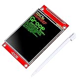
- 2.8 inches 320x240 pixels RGB colorful display lcd screen.
- Support touch screen function, with touch pen inside that you can use it more easily.
- Compatible with Arduino R3 controller board,which will improve your project operations.
- There is a SD card socket on the back of this screen.
- SPI Serial,built-in ILI9341driver IC and power supply IC.
Can touch controls navigate between pictures?
Yes. A cited Arduino Project Hub photo-frame project demonstrates changing images and using touch functions to navigate between them: Display BMP Pictures from SD Card on TFT LCD Shield. The touch controller, pin assignments, and handling code depend on the particular shield. Use code and wiring details that match your own hardware rather than assuming the project’s touch setup transfers unchanged.
Independent reader supportYour contribution helps us test, update, and keep practical guides available for everyone.What to verify if it does not work
- Card is not detected: Check that the shield has an SD slot, the card is seated, and its format matches the shield’s requirements.
- File is not found: Confirm the BMP name and path in the sketch. If following the Adafruit example, place the file in the card’s base directory unless you have changed the path.
- Display remains blank or behaves incorrectly: Confirm that the sketch is for the shield’s display controller and that its pin and chip-select configuration matches the actual hardware.
- SPI-related problems: On the cited Adafruit example, TFT and SD share hardware SPI. Check the example’s SPI assumptions and chip-select configuration against the shield documentation.
- Image is not displayed as expected: Check that it is a 24-bit BMP within the documented dimensions for the shield/example you are using.
These checks address the setup dependencies documented for the cited workflow; they are not a universal diagnosis for every Arduino display shield.
Recommended Free Tools
Quick Recap
Rank #4

- FLEXIBLE POWER CONFIGURATION: Operates by default on a 5V power supply for VCC and Backlight (BL) with the J1 jumper open. To use a 3.3V power supply, you must solder the J1 jumper on the back of the module closed. Please confirm your microcontroller's voltage output and configure the module accordingly before powering on.
- CRISP COLOR DISPLAY & SPI INTERFACE: Features a 1.8-inch TFT screen with 128x160 pixel resolution for clear, vibrant graphics. The module is driven by an ST7735S IC via a 4-wire SPI interface. A bright, 2-LED white backlight ensures visibility. Each screen ships with a protective film to prevent scratches.
- EXPANDABLE I/O & PINOUT VERIFICATION: The board includes an integrated SD card slot for projects requiring local storage. Accessing the SD card requires soldering headers to the second row of unpopulated pin holes. CRITICAL: Pinout markings may differ from other ST7735 modules. Always verify the silkscreen labels on your specific board before wiring.
- WIDE COMPATIBILITY & COMPACT SIZE: The module's logic interface is compatible with both 3.3V systems (like ESP32, STM32) and 5V systems (like Arduino Uno), even when the board is powered by 5V VCC. The compact PCB measures 38.30 x 62.48 mm, with a display active area of 28.03 x 35.04 mm. Operating Temperature: -20°C to 60°C.
- COMPLETE 2-PACK KIT & SUPPORT: Includes 2 x 1.8-inch TFT LCD Display Modules, 2 x 16-Pin Male Headers, and 2 x 8-Pin Male Headers. Digital documentation and technical support for setup, programming, and troubleshooting are available through our store customer service.
Rank #3
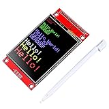
- 2.4 inches 320x240 pixels RGB colorful display lcd screen.
- Support touch screen function, with touch pen inside that you can use it more easily.
- compatible with Arduino R3 controller board,which will improve your project operations.
- there is a SD card socket on the back of this screen.
- SPI Serial,built-in ILI9341driver IC and power supply IC.
Product prices and availability are accurate as of the date/time indicated and are subject to change. Any price and availability information displayed on Amazon at the time of purchase will apply.

