
Quick wins for a faster PC:
Clear out junk files and repair common Windows errorsFree Scan →Scan for outdated or missing drivers - takes under a minuteDriver Scan →iTechGuides is reader-supported. When you buy through links on our site, we may earn an affiliate commission. As an Amazon Associate I earn from qualifying purchases. Learn more
3D-printed drones are developed as engineered aircraft, not simply as plastic parts assembled around motors. A dependable workflow starts with mission and mass requirements, builds a parametric airframe, measures the chosen printed material, optimizes the structure, controls the printing process, and then progresses from coupon tests to restrained hover and autonomous flight. The print process is only one stage; propulsion matching, dimensional inspection, electronics integration, and evidence-based flight testing determine whether the aircraft is safe and useful.
For most prototypes, fused-deposition modeling (FDM) with PETG or PLA is the accessible starting point. Selective laser sintering (SLS) with PA12 can produce complex lightweight structures, while continuous-fiber fabrication (CFF) can reinforce highly loaded arms and landing gear. Each option trades cost and speed against stiffness, environmental resistance, equipment requirements, and repeatability.
What is the complete workflow for a 3D-printed drone?
The practical sequence is requirements definition, parametric CAD, material characterization, structural and aerodynamic optimization, process selection, controlled printing, inspection, subsystem testing, and flight qualification. Skipping an early stage usually moves the failure into a more expensive stage: a weak arm may first appear as vibration, an inaccurate motor interface as a calibration problem, and an underestimated mass as inadequate hover time.
- Define the mission, payload, take-off mass, rotor count, propeller diameter, battery, operating environment, and acceptable risk.
- Model a parametric frame with replaceable arms, interfaces, landing gear, electronics mounts, and battery rails.
- Measure printed-material behavior rather than treating bulk-filament datasheet values as part properties.
- Use finite-element analysis (FEA), topology optimization, and preliminary aerodynamic analysis to reduce mass while preserving stiffness and usable flight performance.
- Select FDM, SLS, CFF, or a combination, then set orientation, layer thickness, infill, temperature, speed, drying or powder preparation, and post-processing.
- Inspect dimensions and mass, test coupons and structural parts, measure propulsion, calibrate electronics, and progress through restrained hover to outdoor missions.
How should you set requirements before opening CAD?
Write a one-page vehicle specification first. It should identify what the drone must carry, where it will fly, and what failure consequences are acceptable; those decisions control every later dimension and material choice.
#1 Best Overall
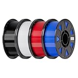
- Ender PETG Filament - combines the advantages of PLA and ABS, offering an eco-friendly, odorless, and user-friendly 3D printing experience. It features enhanced toughness that effectively resists cracking and warping, ensuring smooth and successful prints.
- Excellent Mechanical Properties - This PETG filament boasts high strength, impact resistance, and temperature resistance, with low shrinkage and high elongation at break. Printed models remain sturdy and durable even under repeated bending or stress.
- High Clarity & Glossy Finish - It delivers outstanding transparency and light transmission, making it perfect for visually detailed projects such as lampshades and display cases. The surface finishes with a smooth, glossy appearance.
- Reliable Printing & Compatibility - Dried, vacuum-sealed, and tangle-free, it minimizes clogging, bubbling, and snapping. With a precise diameter of 1.75mm (±0.02mm), it feeds smoothly and is compatible with most FDM printers on the market.
- Safe and Supported - Non-toxic and chemically resistant, Ender-PETG is safe for everyday use. Backed by Creality’s 12-month & 24 hours after-sales service. Note: Please place this product in a dry and ventilated environment, not in an environment of high temperature, sunny or humid conditions.
Define size, mass, and propulsion
The 2026 modular multirotor study examined platforms with 300–600 mm overall dimensions and 1–3 kg take-off masses. It characterized propulsion kits before freezing the airframe, using three propeller classes: 6.5-inch, 9.5-inch, and 10-inch. Treat these as studied design points, not universal recipes: motor torque, battery voltage, propeller pitch, payload, and controller limits still need to be matched for your aircraft.
Specify the environment and risk
Record outdoor ultraviolet exposure, temperature, moisture, dust, expected impact energy, and whether a failed arm can endanger people or property. A research prototype can accept a replaceable sacrificial part; a field system may require redundant fasteners, guarded propellers, or a conservative flight envelope. Define an allowable structural deflection and a minimum control margin before optimization so a lighter design does not quietly become too flexible.
How do you build a parametric drone airframe?
Use a constraint-driven CAD model in which the dimensions that matter to propulsion and electronics are parameters, not hand-edited sketches. The modular study integrated mechanical and electrical plug-in interfaces and battery rails so an arm, payload plate, or battery carrier could be resized or replaced without rebuilding the entire frame.
Model interfaces before cosmetic shells
Start with motor-hole patterns, arm-to-center-joint interfaces, landing-gear attachment points, flight-controller mounting, antenna clearance, battery restraint, and cable paths. Add alignment keys or dowels where repeated assembly matters, and leave access for tools and connectors. Separate load paths from covers: a thin printed fairing should not be the only feature carrying motor thrust or landing impact.
Make variants deliberate
Expose propeller diameter, arm length, battery volume, payload plate spacing, and wall or rib dimensions as named parameters. A single model can then generate a short-arm indoor version and a larger outdoor version while preserving interface locations. Keep a revision record for each exported part so a replacement arm is dimensionally compatible with the aircraft already in service.
Which material and printing process fit a drone frame?
No filament is best for every frame. Choose among printability, dimensional accuracy, toughness, ultraviolet and heat resistance, moisture behavior, stiffness-to-weight, equipment, and repairability.
Rank #2

- ①【PETG Filament 1.75mm】SUNLU PETG 3D Printer Filament combines the advantages of both PLA and ABS 3D printer filament, making 3D printing more convenient and easy.
- ②【Excellent Layer Adhesion】PETG filament offers excellent layer adhesion, reducing the risks of warping and ensuring smooth, strong prints with great structural integrity.
- ③【Enhanced Toughness】Known for its toughness, PETG outperforms many other filaments in durability, making it ideal for creating sturdy and resilient items that can withstand stress and use.
- ④ 【High Impact & Mechanical Strength】Stronger than standard PLA and easier to print than ABS. Our PETG filament provides excellent layer adhesion and impact resistance, preventing warping or cracking under stress. Perfect for printing functional parts, RC drone frames, or heavy-duty household tools.
- ⑤【Weather-Resistant for Outdoor Use】Engineered with robust UV and moisture resistance, SUNLU PETG maintains its structural integrity and color vibrancy over time. It is the ideal choice for outdoor planters, car accessories, and weatherproof garden fixtures that endure harsh sunlight or rain.
| Material or process | Strengths shown by the evidence | Limitations and practical trade-offs |
|---|---|---|
| PLA via FDM | Easy to print; the 2026 micro-frame comparison found the best dimensional consistency among its tested configurations. | Environmental and heat resistance must be considered before outdoor or hot-environment use. |
| PETG via FDM | Practical balance of printability and toughness; selected for the modular prototype’s final airframe because UV resistance supports outdoor durability. | Still requires tuned process settings and dimensional checks at interfaces. |
| ABS via FDM | Usable for printed frames when process control is adequate. | The cited comparison found pronounced warping and a positive slicer mass-prediction bias; enclosure and calibration demands are higher. |
| PA12 via SLS | Supports complex, lightweight geometries without FDM support structures; the topology-optimized study measured anisotropy and validated the printed design with load testing. | Requires SLS equipment and powder preparation; printed properties must be measured for the selected build and orientation. |
| Continuous-fiber fabrication | Continuous fiberglass or carbon reinforcement improves stiffness and strength-to-weight in loaded components such as rotor arms and landing gear. | Specialized equipment, longer production time, higher cost, and more constrained fiber paths reduce accessibility. |
The modular aircraft combined PLA and PETG FDM parts with carbon-fiber-filled nylon and continuous fiberglass reinforcement for higher mechanical performance. A hybrid frame can therefore reserve premium reinforcement for arms or gear while keeping covers and brackets inexpensive and replaceable.
Do these 3 things before closing this tab:
1Repair Windows errors before they cause bigger problems2Scan for outdated or missing drivers - takes under a minute3Clear out junk files and repair common Windows errorsHow do you characterize printed material instead of trusting a datasheet?
Bulk-filament tensile values describe raw material, not necessarily a printed part. Layer adhesion, raster direction, infill, voids, cooling, moisture, and build orientation can change stiffness and failure load.
Print representative coupons
Use the same nozzle, layer height, temperatures, infill strategy, orientation, and post-processing planned for the airframe. Measure dimensions and mass, then run tensile, bending, or compression tests appropriate to the load path. Keep specimens from multiple build locations when production consistency matters.
Check the model against physical behavior
The topology-optimized micro-drone work measured PA12 properties and compared finite-element predictions with bending tests before printing the optimized structure. Follow that logic: identify where simulation and test diverge, update material cards or boundary conditions, and rerun the design rather than hiding the discrepancy with extra wall thickness.
For qualification planning, the National Institute of Standards and Technology (NIST) notes that extensive empirical qualification can require many thousands of tests, millions of dollars, and 5–15 years. A prototype flight is not equivalent to that level of certification evidence.
The Tool Desk
Outbyte Driver Updater FREEScan for outdated or missing drivers - takes under a minuteDriver Scan →Outbyte PC Repair FREERepair Windows errors before they cause bigger problemsFix Now →How are the frame and aerodynamics optimized?
Optimization is a constrained compromise: remove mass where loads are low, retain material around fasteners and joints, and keep enough stiffness to prevent resonant vibration and control problems.
Rank #3

- ①【PETG Filament 1.75mm】SUNLU PETG 3D Printer Filament combines the advantages of both PLA and ABS 3D printer filament, making 3D printing more convenient and easy.
- ②【Excellent Layer Adhesion】PETG filament offers excellent layer adhesion, reducing the risks of warping and ensuring smooth, strong prints with great structural integrity.
- ③【Enhanced Toughness】Known for its toughness, PETG outperforms many other filaments in durability, making it ideal for creating sturdy and resilient items that can withstand stress and use.
- ④【High Impact Strength】With its high impact resistance, PETG is perfect for printing parts that need to endure bumps and drops, ensuring long-lasting performance without cracks or breaks.
- ⑤【Robust Durability】PETG prints are robust and maintain their properties over time, making them suitable for both indoor and outdoor applications where weather resistance is a necessity.
Use FEA and topology optimization responsibly
Apply realistic motor thrust, landing impact, battery weight, payload, and joint constraints. Inspect principal stresses, deflection, buckling risk, and fatigue-sensitive notches. Convert the optimized result into manufacturable ribs, fillets, and support-free surfaces; an unconstrained mathematical shape may be impossible to print or inspect.
Check aerodynamic consequences
Arms, plates, batteries, and payloads alter drag and propeller inflow. The aircraft analysis by Pascariu and Zaharia (ASCE Journal of Aerospace Engineering, 2020) reported a maximum lift-to-drag ratio of 14.67 at a 4-degree angle of attack and 20 m/s cruise airspeed for its studied FDM aircraft. That value belongs to that configuration and test model, not every printed drone. Use preliminary aerodynamic analysis to compare candidate shapes, then verify the selected design in flight.
How should you prepare and print the parts?
Process control determines whether a CAD file becomes a repeatable airframe. Record the settings with every build so a replacement part can be reproduced.
- Prepare material. Dry moisture-sensitive filament according to the material supplier’s procedure; prepare and condition SLS powder as required by the machine and powder-management process.
- Choose orientation. Align continuous fibers and FDM rasters with principal loads where possible, while avoiding weak layer interfaces across motor mounts or arm roots.
- Set process parameters. Control layer thickness, extrusion temperature, chamber or bed temperature, speed, cooling, infill, perimeters, and support strategy. Do not assume a slicer’s default mass is accurate for every material.
- Export and label. Preserve the CAD revision, material lot, printer, nozzle or tool, orientation, and slicer profile with the part.
- Post-process carefully. Remove supports, clean interfaces, and finish only surfaces that do not carry critical dimensions. Recheck holes and bearing or fastener seats after finishing.
The modular study used Bambu Lab FDM printers with Bambu Studio and a Markforged Onyx Pro with Eiger for continuous-fiber parts. Those tools illustrate a workflow in which the slicer or process software is part of the manufacturing record, not merely a button pressed after CAD.
What inspections and bench tests should a printed drone pass?
Test from the cheapest, least hazardous evidence to the most realistic flight condition. Record measured values, acceptance limits, failures, and corrective actions.
Dimensional and visual inspection
- Measure motor mounts, arm interfaces, landing-gear spacing, battery rails, and flight-controller mounts with appropriate gauges or metrology.
- Look for warping, delamination, voids, under-extrusion, poor fiber placement, cracks, and powder-fusion defects.
- Weigh every structural assembly and compare actual mass with the slicer estimate; update the aircraft mass model before selecting battery and PID gains.
A 2026 FFF comparison found strong material-dependent differences: PLA had the best dimensional consistency in its tested configurations, PETG was intermediate, and ABS showed pronounced warping and mass-prediction bias. Those findings make interface inspection especially important when switching materials.
Rank #4

- [Excellent PETG Filament]Our PETG combines the benefits of PLA and ABS to reach Eco-friendly and odorless performance. This PETG Filament is feature in good toughness to avoid cracking and warping, enbale excellent 3D printing.
- [Toughness-enhanced PETG] Our PETG filament choose durable and strong material that delivers excellent clarity, light transmission, and a glossy finish. It is recommended to use a printing temperature of 220-250°C and a base plate temperature of 70-80°C for better printing results.
- [Tangle-Free & Neatly Wound] We ensure that every PETG filament is tightly and neatly wrapped by utilizing full mechanical winding, which effectively minimizes tangles, filament snapping, and line breakage.
- [No Clogging & No Bubbles] Our filaments are thoroughly dried and carefully vacuum sealed to protect them from moisture and dust, which ensures that there will be no issues with clogging or bubbling during printing. Our PETG is designed to be perfectly compatible with the majority of 1.75mm FDM 3D printers, especially suitable for Creality 3D Printers!
- [High Precision & Consistent Performance]Our PETG filament boasts a diameter of 1.75mm, ensuring utmost accuracy with a tolerance of only +/- 0.03mm. With strict quality control and impeccable dimensional precision, our PETG filament guarantees a smooth and steady feeding during printing.
Load and propulsion tests
- Test coupons and representative arms in tensile or bending fixtures, then apply static loads to the assembled frame at motor and landing-gear attachment points.
- Use a propulsion stand to measure thrust, current, voltage, and temperature for each motor, ESC, propeller class, and battery combination.
- Check fastener retention, arm deflection, vibration, and resonance before installing propellers for a free flight.
Static tests should include a clear stop condition. If a crack, permanent deformation, unexpected vibration, or temperature rise appears, replace the part or revise the process before proceeding.
Free tools Windows power users keep installed
One-click scans. No signup required.
How do you integrate electronics and conduct flight tests?
Integration turns a strong frame into an aircraft with predictable control behavior. Install motors, ESCs, propellers, flight controller, GPS, telemetry, battery, and other sensors while keeping center of gravity, cooling, antenna separation, and service access within the design envelope.
- Verify polarity, connector security, insulation, and power-distribution ratings without propellers installed.
- Calibrate inertial sensors on a level surface and calibrate ESCs using the flight controller’s documented procedure.
- Confirm motor order, rotation direction, failsafe behavior, battery warnings, GPS function, and telemetry before arming.
- Tune PID gains conservatively, beginning with restrained or low-altitude hover tests and checking motor temperature, current, vibration, and attitude response.
- Expand to indoor hover, outdoor hover, and then planned autonomous waypoint missions. The modular-airframe study reported indoor and outdoor hover tests followed by outdoor autonomous waypoint flights.
Keep a test log containing configuration revision, battery, weather, payload, flight time, faults, and software settings. Change one major variable at a time; otherwise a revised frame, new propeller, and retuned controller cannot be separated as causes of an improvement or failure.
Independent reader supportYour contribution helps us test, update, and keep practical guides available for everyone.What evidence is enough to call a 3D-printed drone qualified?
“Qualified” depends on the mission and applicable aviation rules. A successful hover demonstrates basic controllability; it does not establish durability, repeatability, or compliance for every environment.
NIST describes three qualification paths: statistical-based qualification built on extensive empirical testing; equivalence-based qualification using moderate testing to show a new material or process matches a previously qualified one; and model-based qualification in which computer predictions are verified with minimal testing. Select the path that matches the consequence of failure and document its limits.
What’s actually slowing this PC down?
Pick the symptom - the matching free tool is one click away.
Prototype evidence
For a low-risk prototype, a defensible package includes material coupons, dimensional records, static-load results, propulsion-stand data, calibration records, restrained and hover tests, and mission logs. The topology-optimized micro-drone, modular multirotor, and FDM aircraft studies demonstrate complementary evidence: FEA validated against load tests, indoor/outdoor and waypoint flights, and aerodynamic analysis paired with flight testing.
Best Value

- High Performance & Strength: PETG filament combines the strengths of PLA and ABS. It offers low shrinkage, high impact resistance, excellent temperature resistance, and high elongation at break, models can bend repeatedly and remain firm and sturdy
- High Transparent & Glossy: PETG has a high degree of transparency. The finished product has a fine surface with exquisite details. This makes PETG material ideal for making transparent parts and models, such as lampshades, display boxes, and more
- Non-toxic Material: Creality CR-PETG 3D printing filament has excellent wether resistance and chemical resistance, no odor, and non-toxic, green environmental protection
- Wide Compatible: CR-PETG filament is wildly used in FDM 3D printers on the market.Compatible with most popular 3D printers such as MK3, Creality Ender series/CR series, ELEGOO, Anycubic, and more
- Creality Support: Creality provides 12-month & 24 hours after-sales service. Note: Please place this product in a dry and ventilated environment, not in an environment of high temperature, sunny or humid conditions
Production evidence
Beyond prototypes, add process repeatability, calibrated metrology, material-lot traceability, maintenance intervals, replacement-part interchangeability, and the aviation qualification path required in the operating jurisdiction. Production cannot rely on one successful print; it must show that subsequent builds remain within the same structural and dimensional limits.
Which manufacturing route should you choose?
Use FDM when low cost, fast iteration, and accessible equipment matter most. Choose SLS when complex PA12 geometry and consistent powder-bed production justify specialist equipment. Add CFF when a small number of highly loaded parts need a large stiffness-to-weight improvement and the longer, more expensive process is acceptable.
| Decision factor | FDM | SLS PA12 | CFF reinforcement |
|---|---|---|---|
| Prototype accessibility | Highest; desktop systems are widely available. | Lower; requires an SLS service or machine. | Lower; requires a compatible continuous-fiber system. |
| Complex geometry | Support and orientation constraints apply. | Well suited to complex lightweight forms. | Constrained by tool paths and fiber placement. |
| Loaded structural parts | Can work with tuned orientation and adequate section thickness. | Requires measured anisotropic properties. | Best suited to selectively reinforced arms and landing gear. |
| Repairability | Usually straightforward to reprint individual parts. | Replacement depends on powder process or service access. | Replacement is more specialized and costly. |
What are the most common failure modes and fixes?
- Arm cracks at the motor or center joint: inspect layer orientation and fastener stress, compare measured bending loads with FEA, and reinforce or redesign the interface.
- Frame vibrates despite correct software settings: check propeller balance, motor alignment, arm stiffness, fastener seating, and resonance before changing PID gains.
- Parts do not assemble: measure functional interfaces, account for process shrinkage or warping, and update the parametric tolerance rather than forcing hardware into place.
- Predicted flight time is too optimistic: replace slicer mass with measured mass, include wiring and payload, and use propulsion-stand current data for the battery estimate.
- Outdoor parts degrade: reassess ultraviolet, heat, and moisture exposure; PETG was selected for the modular prototype partly for outdoor UV durability, while PLA requires more environmental caution.
A disciplined design review asks whether the failure came from requirements, material data, geometry, process settings, assembly, or control tuning. Fix the earliest incorrect assumption and repeat the relevant test stage.
Frequently Asked Questions
Can a 3D-printed drone frame really carry a useful payload?
Yes, if the frame is sized around measured propulsion thrust, structural load tests, and the complete take-off mass. Payload capacity is not a property of the filament alone; battery, motor, propeller, arm stiffness, and safety margin determine it.
Should I print the propellers as well as the frame?
Treat propellers as a separate, balance-critical component. Unless you have a validated manufacturing and balancing process, use appropriately rated manufactured propellers and concentrate printed development on the airframe and replaceable mounts.
How do I make replacement printed arms interchangeable?
Freeze the motor-hole pattern, arm-to-center interface, fastener hardware, and datum surfaces in the parametric CAD model. Inspect those features on every production batch and keep the CAD revision and print profile with the replacement part.
Is one successful autonomous flight enough for approval?
No. It demonstrates one configuration under one set of conditions. Approval or operational confidence requires the level of material, process, environmental, and flight evidence appropriate to the consequences of failure and any applicable aviation rules.
Crashes, No Sound, or Screen Glitches?
Random freezes, missing sound and display glitches usually trace back to one bad driver. Find and replace yours safely.Free scan · under a minuteWindows Errors? Fix Them Before They Spread
Repair common Windows errors and clear accumulated junk for a smoother, more stable PC - no reinstall needed.Free scan · no reinstallQuick Recap
Product prices and availability are accurate as of the date/time indicated and are subject to change. Any price and availability information displayed on Amazon at the time of purchase will apply.

