
iTechGuides is reader-supported. When you buy through links on our site, we may earn an affiliate commission. As an Amazon Associate I earn from qualifying purchases. Learn more
You can make a small generator by winding enamelled copper wire into a coil and moving a permanent magnet relative to it. The changing magnetic field induces electricity: move the magnet through the coil, or turn a magnet on a rotor beside a fixed coil. Expect a classroom-scale demonstration—not a source of household power. The magnet does not create energy; turning the crank or moving the magnet supplies mechanical energy that the generator converts into electrical energy.
| Option | What you need | Best for |
|---|---|---|
| Move a magnet through a coil | Enamelled copper wire wound into a coil, a permanent magnet, and an LED or sensitive multimeter | A quick demonstration of induction and changing current direction |
| Fixed coil with a hand-cranked magnetic rotor | Enamelled copper wire, permanent magnets, a shaft or crank, a rigid base, and an LED or multimeter | Comparing how coil turns, magnet arrangement, and rotor speed affect output |
What do you need before you start?
For the simplest demonstration, gather enamelled copper magnet wire, a permanent magnet, tape or another way to hold the coil, and an LED or sensitive multimeter. A coil of wire and a moving magnet are enough to show induction; a stationary magnet inside a stationary coil will not produce a continuing current in this setup.
If you want a fixed coil and hand-cranked magnetic rotor, also prepare a rigid frame or base, a shaft, axle, or spindle that can turn freely, and a way to secure the magnets to the rotor. Keep the rotating parts close to, but not touching, the coil. A hand drill can turn a rotor in some classroom demonstrations, but it is not necessary for a hand-cranked build.
The Open University’s beginner example specifies 25 m of enamelled copper wire about 0.3 mm in diameter, a 15 cm iron nail, an 8–10 cm bolt and nut, cardboard, insulating tape, a hand drill, and a 6 V, 0.06 A torch bulb and holder. Those are parts for that particular arrangement, not universal requirements for every design. Its instructions explain how the coil and spinning magnet are arranged with a small clearance between them.
Popular on Amazon
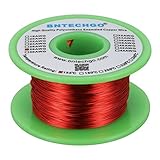
- High Quality enameled Copper Wire!Durable and not break while winding the coils.Highly Efficient!
- Magnet wire is copper wire that coated with a thin layer of insulated enamel.This 28AWG magnet wire is 4 ounces(527 feet).
- This enamelled copper wire the insulation is made from Solderable Polyurethane,and protects the coiled wire from short-circuiting.Temperature rating 155°C (311°F) makes it suitable for several thermal overload applications.Raw copper is drawn to meet specific size requirements based on NEMA MW-79-C standard.
- 28 gauge enameled magnet wire: Wrapped in spool and color is red.Outside diameter 0.0122"for perfect thickness.
- BNTECHGO magnetic copper wire is widely used in the construction of transformers,wound coils,motors,solenoids,instruments,inductors,speakers,electromagnets,and other applications that require tight coils of insulated wire.
There are several workable layouts, and their dimensions should not be casually combined. For example, a magnet moving through a coil is a useful basic demonstration; a fixed coil beside a rotating, magnet-equipped rotor is a different arrangement. NASA’s classroom activity uses a drill to rotate a magnet within a coil and a meter to measure output, while Science Buddies describes a rotor with six neodymium magnets and coils wound around an iron core. Treat each as its own design rather than assuming their parts form one tested plan.
How do you make a generator with a fixed coil and hand-cranked rotor?
- Wind the coil. Wrap enamelled copper magnet wire into a neat, compact coil. Keep the turns orderly and close together, and leave two free wire ends for the connections. More turns tend to increase induced voltage, but the actual output also depends on magnet strength, speed, geometry, alignment, and the connected load.
- Prepare the wire ends. The wire’s thin enamel coating insulates the turns. Remove the coating from the ends where you will make electrical connections, using an appropriate method and care not to nick or break the wire. Connect the bare ends to the indicator with clips, terminals, or soldered connections. Make sure each connection is firm; a loose or enamel-covered contact can prevent current from reaching the indicator.
- Secure the coil and core. Fix the coil to a rigid frame or base so it cannot slide, wobble, or be pulled into the rotor. If the chosen design uses a soft iron core, place it through the coil and secure it. An iron core can increase induced voltage in the Open University explanation, but it does not guarantee a particular output. Do not assume that any iron part or arrangement will produce the same result.
- Build and balance the rotor. Attach the permanent magnets securely to the rotor in the intended pole arrangement, then mount the rotor on a shaft, axle, or spindle. Keep the rotating assembly centered so it turns smoothly rather than wobbling. Check that magnets, fasteners, and the rotor cannot come loose, and that the rotor clears the coil throughout a full turn.
- Set the air gap and alignment. Position the coil close to the rotor magnets without allowing contact. The air gap is the clearance between the rotating magnets and the coil or core; keep it small enough for a strong changing magnetic field but large enough to prevent rubbing. Align the coil with the magnets’ path and keep that position fixed during comparisons.
- Connect an indicator and load. Connect an LED or sensitive multimeter to the coil leads before turning the rotor. An LED gives a qualitative indication: a flash shows that a changing output reached it, but does not measure how much power the generator can deliver. A multimeter set appropriately for the expected small output can show voltage; a meter capable of measuring current can provide another useful reading. If you connect a bulb or another load, record which load you used because output depends on the load as well as the generator.
- Turn the crank gradually. Rotate the shaft by hand at a slow, steady pace first. Watch for rubbing, wobble, loose magnets, or a rotor that stalls. Stop before adjusting the air gap, connections, or magnets. Increase speed gradually only after the mechanism turns freely and remains secure.
In a hand-cranked generator, the crank turns the rotor; the rotor’s magnets pass the fixed coil and continually change the magnetic conditions at the coil. A bolt or drill-driven arrangement can demonstrate the same principle, but keep hands, clothing, and loose wires clear of rotating parts. In NASA’s classroom procedure, wires can wrap around the rotating axle, so secure them away from the shaft and stop the drill before changing connections.
How do you make the simpler moving-magnet version?
Wind a coil, secure it so it cannot move, and connect its two wire ends to an LED or sensitive multimeter. Then push a permanent magnet into the coil and pull it back out. You can also move the magnet through a tube with the coil around the tube, provided the magnet can travel freely and the coil stays in place.
The Tool Desk
Outbyte PC Repair FREERepair Windows errors before they cause bigger problemsFix Now →Outbyte Driver Updater FREEScan for outdated or missing drivers - takes under a minuteDriver Scan →Also popular on Amazon
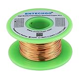
- High Quality enameled Copper Wire!Durable and not break while winding the coils.Highly Efficient!
- Magnet wire is copper wire that coated with a thin layer of insulated enamel.This 22AWG magnet wire is 4 ounces (122 feet).
- This enamelled copper wire the insulation is made from Solderable Polyurethane,and protects the coiled wire from short-circuiting.Temperature rating 155°C (311°F) makes it suitable for several thermal overload applications.Raw copper is drawn to meet specific size requirements based on NEMA MW-79-C standard.
- 22 gauge enameled magnet wire: Wrapped in spool and color is natural.Outside diameter 0.0256"for perfect thickness.
- BNTECHGO magnetic copper wire is widely used in the construction of transformers,wound coils,motors,solenoids,instruments,inductors,speakers,electromagnets,and other applications that require tight coils of insulated wire.
Only the changing magnetic conditions produce current in this described setup. A magnet left stationary inside the coil does not keep generating current. Pushing the magnet in and pulling it out reverses the current direction, so the output is alternating current. A basic LED may respond inconsistently to this changing output; a meter that can detect small changes can be more informative.
The generator principle is the same whether the magnet moves through a coil or the coil sits near a spinning magnet: there must be relative motion. The U.S. Energy Information Administration explains that generators convert kinetic energy into electrical energy. The person turning the crank or moving the magnet supplies that input; the magnet provides a field, not free energy.
What changes the amount of electricity the generator produces?
Several design choices affect induced voltage, but no single change guarantees a specific output. Compare builds by changing one variable at a time and keeping the indicator, connected load, alignment, and measurement method consistent.
Also popular on Amazon

- ENAMELED COPPER MAGNET WIRE (18 AWG): This 1 lb spool holds about 202 ft of solid enameled copper magnet wire in 18 gauge - heavy build (Grade 2) insulation for winding and rewinding coils.
- 220°C (428°F) THERMAL CLASS: Dual polyesterimide + polyamide-imide enamel coating withstands high heat, abrasion and solvents, delivering reliable insulation and long service life in demanding jobs.
- MANY USES: Rewind and build electric motors, transformers, generators, solenoids, chokes, inductors, speakers and guitar pickups, electromagnets, Tesla coils and other DIY electronics projects.
- EASY TO WIND & SOLDER: Flexible copper takes tight, even turns; the enamel strips off easily with fine sandpaper, a blade or heat so you can tin and solder clean connections.
- PRECISION-DRAWN & CONSISTENT: Manufactured by Emtel, an established enameled wire producer, with tight diameter tolerance for even windings, predictable resistance and dependable performance.
- Number of coil turns: More turns tend to increase induced voltage. Wind neatly and count or record the turns so you can compare versions.
- Rotor speed: Faster relative motion tends to increase induced voltage. Turn the crank at a consistent pace when comparing configurations; do not trade safety or mechanical stability for speed.
- Magnet strength and pole arrangement: A stronger magnet or a different arrangement may change the output. Record the magnet configuration rather than assuming that more magnets always mean more useful power.
- Coil area and alignment: The coil’s size and how it faces the magnets’ path affect how the changing field passes through it. Secure the coil in one position while testing so alignment is not an uncontrolled variable.
- Air gap: A larger separation changes the magnetic coupling. Use a small, safe clearance and keep it consistent; a gap that is too small can make the rotor rub or stall.
- Core: A metal core such as soft iron can increase induced voltage in the cited beginner explanation. Compare a coil with and without the core only if the rest of the setup stays the same.
- Connected load: An LED, bulb, and meter do not present the same load or provide the same kind of observation. Keep the load identical when comparing readings, and do not equate a brief flash with the ability to power a device continuously.
Science Buddies describes neatly wound coils around an iron core and uses an LED as a qualitative indication of fluctuating output. NASA’s activity measures output and varies wire turns and magnet configuration. In a separate, specific classroom setup, NASA reports example readings of 15.7 millivolts and 2.54 milliamps at a stated maximum of 450 rpm. Those are context-specific readings, not a specification or expected result for another build.
Why is the LED not lighting or the meter not moving?
No LED light and no meter movement usually mean the output is too small for the indicator, the circuit is not actually connected, or the magnet is not moving relative to the coil. Check the setup systematically before changing several design variables at once.
- Check the connections. Confirm that both coil ends connect to the indicator and that clips, terminals, or soldered joints touch bare conductor rather than enamel. Inspect for a broken wire or a loose connection.
- Check for motion and clearance. Move the magnet through the coil or turn the rotor. A stationary magnet and coil do not produce a continuing output in this demonstration. For a rotor, confirm that it turns freely and the magnets pass the coil without contact.
- Check the indicator and its setup. An LED may not visibly respond to a very small or brief output. Check its connection and try a sensitive multimeter set to a suitable measurement mode and range. If using a meter, make sure the leads are plugged into the correct meter sockets for the measurement.
- Increase output methodically. Try more coil turns, quicker but controlled motion, closer alignment, or a stronger magnet, one change at a time. These are tendencies rather than guaranteed fixes, and output still depends on the geometry and load.
- Check the mechanical build. A rotor that stalls may be rubbing against the coil, have an unbalanced or misaligned rotor, or have a shaft that does not turn freely. Stop before adjusting it; restore a safe air gap and secure the components.
If an LED flashes in only one direction or appears not to light at all, do not assume that the generator has no output. The magnet’s motion reverses current direction as it moves in and out, and an LED may not clearly show both parts of a changing output. Try reversing the LED connections as a diagnostic, then use a sensitive meter to check whether a changing voltage is present. A flash is evidence of a momentary indication, not a reliable power measurement.
Also popular on Amazon

- High Quality enameled Copper Wire!Durable and not break while winding the coils.Highly Efficient!
- Magnet wire is copper wire that coated with a thin layer of insulated enamel.This 30AWG magnet wire is 4 ounces(840 feet).
- This enamelled copper wire the insulation is made from Solderable Polyurethane,and protects the coiled wire from short-circuiting.Temperature rating 155°C (311°F) makes it suitable for several thermal overload applications.Raw copper is drawn to meet specific size requirements based on NEMA MW-79-C standard.
- 30 gauge enameled magnet wire: Wrapped in spool and color is red.Outside diameter 0.0098"for perfect thickness.
- BNTECHGO magnetic copper wire is widely used in the construction of transformers,wound coils,motors,solenoids,instruments,inductors,speakers,electromagnets,and other applications that require tight coils of insulated wire.
How can you test one design against another fairly?
Change one factor at a time and use the same measurement method and load for each trial. Otherwise, a brighter flash or larger reading cannot be confidently attributed to a particular coil, magnet, or speed change.
- Record coil turns, core use, magnet strength or configuration, air gap, and how the rotor is driven.
- Keep the coil area, coil alignment, indicator, and connected load unchanged between trials unless one of those is the variable under test.
- For a hand-cranked rotor, aim for a repeatable crank rate and note that hand speed may vary. Avoid ranking designs from uncontrolled impressions.
- Use a meter for comparable voltage readings where possible. If you use an LED, describe whether it flashes or glows as a qualitative observation rather than assigning it an electrical output.
Build geometry, speed, wiring, and load all influence results. Without controlled measurements, it is not sound to claim that one design is categorically the most powerful or to predict a particular reading for a different build.
Recommended Free Tools
What safety precautions matter?
Keep the magnets and rotating parts controlled, and stop the mechanism before touching the coil, rotor, or wiring. Small neodymium magnets can pinch fingers and can crack or shatter if dropped or snapped together. Science Buddies advises keeping them away from small children, pets, credit cards, and pacemakers; use adult supervision where appropriate.
Also popular on Amazon

- High Quality enameled Copper Wire!Durable and not break while winding the coils.Highly Efficient!
- Magnet wire is copper wire that coated with a thin layer of insulated enamel.This 20AWG magnet wire is 4 ounces (80 feet).
- This enamelled copper wire the insulation is made from Solderable Polyurethane,and protects the coiled wire from short-circuiting.Temperature rating 155°C (311°F) makes it suitable for several thermal overload applications.Raw copper is drawn to meet specific size requirements based on NEMA MW-79-C standard.
- 20 gauge enameled magnet wire: Wrapped in spool and color is red.Outside diameter 0.0315"for perfect thickness.
- BNTECHGO magnetic copper wire is widely used in the construction of transformers,wound coils,motors,solenoids,instruments,inductors,speakers,electromagnets,and other applications that require tight coils of insulated wire.
Secure the coil, magnets, and frame before turning the rotor. Keep hands, clothing, and loose wires clear of spinning parts, especially when using a drill. Stop the drill before adjusting connections or repositioning anything. If the wire becomes hot, stop immediately and disconnect the setup: a hot wire is a warning that the circuit or connected load needs attention, not a reason to keep testing. Allow it to cool before inspecting for a short, damaged insulation, or a poor connection.
A small magnet-and-coil generator is best treated as a hands-on physics experiment. It may light a small bulb or produce a brief LED flash, depending on the exact build, but it is not a practical household supply or a way to charge devices reliably.
How we chose the build guidance
The two approaches here reflect the documented classroom options: a moving magnet and coil, and a magnet rotor turning near a coil. The build advice prioritizes the induction principle, parts and dimensions explicitly documented for the Open University example, the controlled comparisons described by NASA and Science Buddies, and safety cautions in the cited educational material. No single output is promised because the sources describe distinct setups and results depend on the complete geometry, motion, and load.
Do these 3 things before closing this tab:
1Scan for outdated or missing drivers - takes under a minute2Repair Windows errors before they cause bigger problems3Fix the driver behind crashes, sound loss and screen glitchesFrequently Asked Questions
Can a small magnet generator charge a phone?
A classroom coil-and-magnet build is not a dependable phone charger: its output varies with the build and motion, and a brief LED flash does not establish usable charging power. Use a purpose-built, appropriately regulated power source for charging electronics.
Why does moving a magnet through a coil make alternating current?
As the magnet enters and then leaves the coil, the magnetic conditions at the coil change in opposite ways, reversing the direction of induced current. The voltage also changes as the magnet moves, so this small demonstration produces changing output rather than steady direct current.
Can I use a neodymium magnet for this project if I have a pacemaker?
Science Buddies cautions against bringing magnets near pacemakers. If you have a pacemaker, do not handle or work near the magnets; choose a non-magnet activity or consult your healthcare provider about safe distances.

