
Crashes, No Sound, or Screen Glitches?
Random freezes, missing sound and display glitches usually trace back to one bad driver. Find and replace yours safely.Free scan · under a minuteWindows Errors? Fix Them Before They Spread
Repair common Windows errors and clear accumulated junk for a smoother, more stable PC - no reinstall needed.Free scan · no reinstallShort answer: a standalone inductor in series with an LED does not set a safe DC current. In steady state it is nearly a short circuit, so the LED still needs a resistor, a linear constant-current regulator, or a switching LED driver. The inductor value can be calculated only as part of a switching converter, using the converter topology, voltage range, switching frequency, permitted ripple current, and the controller’s limits.
First identify the circuit
“Inline with an LED” can describe two very different circuits. A battery, inductor, and LED is not a regulated current source. An inductor resists changes in current and smooths switching current, but it does not establish a safe steady-state LED current from a DC supply.
| Circuit | Standalone series inductor? | Correct approach |
|---|---|---|
| Battery → resistor → LED | No | Calculate the resistor using R = (VSUPPLY − VF)/ILED. |
| Battery → inductor → LED | No | Add current regulation; an inductor alone cannot prevent overcurrent. |
| Buck LED driver | Yes | Use the buck equation and the IC data sheet’s limits. |
| Boost LED driver | Yes | Use the boost equation; input-side current is usually higher than LED current. |
| Buck-boost or SEPIC | Yes, topology-specific | Use that controller’s waveform and design equations. |
| LED strip with built-in resistors | Usually no | Use its rated supply; add filtering only if required. |
Choose a buck when the input remains above the LED-string voltage, a boost when the input is below it, and a buck-boost when the input can be either above or below it. TI’s LED Driver Basics explains these topology constraints.
Values you must gather before calculating
- Topology: buck, boost, buck-boost, SEPIC, or the exact topology shown in the controller data sheet.
- Input limits: minimum and maximum voltage, including surges if relevant.
- LED voltage: the full string’s forward-voltage range at operating temperature, plus sense-resistor voltage and any required headroom or switch losses.
- Maximum regulated LED current: include LED, sense-resistor, reference, loop-accuracy, dimming, startup, and fault tolerances.
- Switching frequency: use the minimum and maximum values permitted by the controller.
- Ripple target: a common first estimate for a buck is 20–40% of maximum LED current, not a universal rule. The controller’s recommended range and minimum-ripple requirement take priority.
Buck LED-driver calculation
For a conventional buck in continuous conduction, a starting equation is:
#1 Best Overall

- High-Performance Power Inductor: designed with 4.7UH inductance and high current capacity, ideal for power supply circuits, DC-DC converters, LED drivers and automotive electronics, ensuring stable energy storage and noise suppression.
- Durable Molded Structure: a rugged molded resin construction that enhances mechanical stability, reduces core loss, and resists vibration, heat and humidity for long-term reliability in harsh environments.
- Compact SMD Design: surface-mount package with 0420 footprint (4 x 4 x 2 mm) for space-saving PCB layouts, compatible with automated assembly processes to improve production efficiency.
- Wide Application Compatibility: operates within a temperature range of -40 C to +125 C and supports high-frequency circuits, suitable for consumer electronics, industrial equipment, IoT devices and communication systems.
- Cost-Effective Bulk Pack: includes 30 pieces per pack, offering a budget-friendly solution for prototyping, repairs or mass production while maintaining consistent quality and performance.
L = VLED(VIN,MAX − VLED) / (ΔIL fSW VIN,MAX)
Here, VLED is the effective regulated output voltage (LED string plus any sense voltage included by the controller), and ΔIL is peak-to-peak ripple. For a fixed inductor, ripple is often greatest at maximum input voltage, but calculate all input and LED-voltage corners. TI gives equivalent relationships and ripple-ratio methods in the TPS922152 data sheet.
Worked buck example
Assume a 12–16 V input, a 3.2 V LED string, 1.0 A maximum LED current, 500 kHz switching, and 30% target ripple:
- ΔIL = 0.30 × 1.0 A = 0.30 A.
- L = 3.2 × (16 − 3.2) / (0.30 × 500,000 × 16) ≈ 17.1 µH.
- Choose a nearby standard value allowed by the IC, such as 15 µH or 18 µH, then recalculate with the actual value.
With 15 µH, ΔIL ≈ 0.341 A. The resulting currents are:
Rank #2

- High-Performance Power Inductor: designed with 10UH inductance and high current capacity, ideal for power supply circuits, DC-DC converters, LED drivers and automotive electronics, ensuring stable energy storage and noise suppression.
- Durable Molded Structure: a rugged molded resin construction that enhances mechanical stability, reduces core loss, and resists vibration, heat and humidity for long-term reliability in harsh environments.
- Compact SMD Design: surface-mount package with 0420 footprint (4 x 4 x 2 mm) for space-saving PCB layouts, compatible with automated assembly processes to improve production efficiency.
- Wide Application Compatibility: operates within a temperature range of -40 C to +125 C and supports high-frequency circuits, suitable for consumer electronics, industrial equipment, IoT devices and communication systems.
- Cost-Effective Bulk Pack: includes 30 pieces per pack, offering a budget-friendly solution for prototyping, repairs or mass production while maintaining consistent quality and performance.
- Peak: IL,PEAK = ILED + ΔIL/2 ≈ 1.171 A.
- RMS: IL,RMS = √(ILED2 + ΔIL2/12) ≈ 1.005 A.
This illustrative result does not override the controller’s recommended inductance, current limit, or minimum-ripple rules.
Boost LED-driver calculation
In a boost driver the inductor is normally on the input side, so its average current is not the LED current. For an ideal boost:
D = 1 − VIN/VOUT
IL,AVG ≈ IIN ≈ VOUTILED/(ηVIN)
A common continuous-conduction estimate is:
L ≈ VIND/(ΔILfSW)
Check minimum input voltage, maximum LED-string voltage, efficiency, duty-cycle limits, current limit, and every operating corner. The worst case can occur at minimum input or maximum output, depending on the controller and control mode. Infineon’s boost LED-driver guidance provides a topology-specific selection procedure.
Rank #3

- High-Performance Power Inductor: designed with 15UH inductance and high current capacity, ideal for power supply circuits, DC-DC converters, LED drivers and automotive electronics, ensuring stable energy storage and noise suppression.
- Durable Molded Structure: a rugged molded resin construction that enhances mechanical stability, reduces core loss, and resists vibration, heat and humidity for long-term reliability in harsh environments.
- Compact SMD Design: surface-mount package with 0630 footprint (7 x 7 x 3 mm) for space-saving PCB layouts, compatible with automated assembly processes to improve production efficiency.
- Wide Application Compatibility: operates within a temperature range of -40 C to +125 C and supports high-frequency circuits, suitable for consumer electronics, industrial equipment, IoT devices and communication systems.
- Cost-Effective Bulk Pack: includes 30 pieces per pack, offering a budget-friendly solution for prototyping, repairs or mass production while maintaining consistent quality and performance.
Buck-boost and SEPIC designs
Do not substitute the buck equation. These converters have different inductor voltage waveforms, duty cycles, average currents, and often multiple inductors or coupled windings. Use the exact controller equation, reference design, and current-limit method. The TPS92365x documentation illustrates why LED-driver topology and operating mode matter.
How to choose the physical inductor
Inductance under bias
A part marked “10 µH” may measure substantially less at operating current. Include initial tolerance, DC-bias loss, temperature dependence, and the manufacturer’s measurement conditions. Recalculate ripple with the minimum effective inductance, not just the nominal marking.
Recommended Free Tools
Saturation current
Saturation current is defined by a specified inductance drop, and vendors use different criteria. Compare the underlying definition and inspect the inductance-versus-current curve. As a conservative rule, keep the specified saturation point above calculated peak current, the converter current limit, and plausible startup, transient, and fault currents. TI discusses these checks in the TPS922152 data sheet.
Rank #4
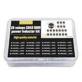
- 20Values each 10pcs,all 200pcs. 1UH - 2.2MH CD43 Wire Wound SMD Power Inductor Assortment Kit, size 4.5mmx4mmx3.2mm
- Including 1UH (1R0),1.5UH (1R5),2.2UH (2R2),3.3UH (3R3),4.7UH (4R7),6.8UH (6R8),10UH (100),15UH (150),22UH (220),33UH (330)
- Including 47UH (470),68UH (680),100UH (101),150UH (151),220UH (221),330UH (331),470UH (471),680UH (681),1MH (102),2.2MH (222)
- Wire Wound SMD Power Inductor Small size, high current resistance, low DC resistance. Lead-free product, RoHS compliant. Carrier tape packaging, suitable for reflow soldering SMT process.
- Wire Wound SMD Power Inductor can be widely used in in buck-boost converters, monitors, notebook computers, network communication equipment, etc.
RMS heating, DCR, and core loss
Compare the manufacturer’s RMS rating and stated temperature rise with your board conditions. Copper loss is approximately PCU = IRMS2 × DCR. Core loss from ripple and switching frequency adds heat; a small high-frequency part can overheat even when its catalog current appears adequate. See Analog Devices AN-140 and AN-44.
Construction and safety
- Shielded power inductors can reduce magnetic coupling, but they do not replace tight high-di/dt layout or EMI testing.
- Check DCR, package temperature rating, maximum working voltage, insulation, creepage, and clearance when the circuit is not SELV.
- For audible products, check magnetostriction and the controller’s burst, pulse-skip, and PWM behavior.
Controller-specific checks are mandatory
The calculation is only a starting point. Read the controller data sheet before ordering parts. Verify:
- Recommended, minimum, and maximum inductance.
- Minimum ripple needed for stable or predictable regulation. TI’s TPS92200 data sheet gives an example where too little ripple calls for a smaller inductor.
- Peak current-limit behavior and blanking time.
- Compensation or loop-stability restrictions.
- PWM dimming, analog dimming, pulse-skipping, and minimum controllable current.
- Output-capacitor value, ESR, ripple-current rating, and placement. TI describes output capacitance as part of LED-ripple and dynamic control in LED Driver Basics.
Do not assume the largest inductor is safest: excessive inductance can increase size, DCR, cost, stored energy, and control-loop problems. Too little inductance raises ripple, peak stress, EMI, and the chance of discontinuous operation; Analog Devices discusses these effects in its inductor-violation analysis.
Best Value

- 【Fast Detection】Designed for quick troubleshooting of inductors on PCB boards with high sensitivity contact detection, helping locate potential faulty components more efficiently than traditional multimeter testing methods
- 【Simple Operation】Connect the inductance tester via Type-C power supply until the blue power indicator lights up, confirming the tester is working properly. The PCB board must also be powered on before testing. Simply touch the target inductor component during operation, and the green LED will light up when the inductor is functioning normally
- 【Compact Probe Design】Features a compact probe tip for easier access to narrow spaces and densely packed PCB components, making inductor inspection more convenient during repair work
- 【Inductor Only & LED Judgment】 Designed only for inductors marked with “L” on PCB boards. Not suitable for capacitors, resistors, voltage testing, or other electronic components. This tester does not display inductance values, and the green LED is used only to indicate whether the tested inductor is in normal working condition
- 【Wide Applications】 Suitable for PCB inductor inspection in smartphones, laptops, chargers, power adapters, automotive electronics, LED driver boards, and small home appliances, etc
Low-current dimming and edge cases
At very low analog-dimmed currents, ripple can become a large fraction of average current. PWM dimming, burst mode, and pulse-skipping can produce visible flicker, audible noise, or poor regulation even when full-current operation is correct. Check the driver’s minimum current and dimming specifications rather than extrapolating from the 100% current calculation.
A ferrite bead is not a substitute for a power inductor: its impedance, DC-current capability, saturation behavior, and heating are different.
Quick Recap
Layout and prototype verification
- Keep the high-di/dt loop containing the switch, inductor, diode or synchronous MOSFET, and capacitors physically small.
- Place current-sense components and feedback wiring exactly as the controller layout guide specifies.
- After assembly, measure inductor current, LED-current ripple, startup and dimming peaks, inductor temperature, and switch-node ringing.
- Investigate EMI and acoustic noise under every intended operating mode.
Symptom-to-cause guide
| Symptom | Likely causes |
|---|---|
| LED fails or overheats | No current feedback, excessive peak current, or wrong topology. |
| Inductor runs hot | High DCR, core loss, saturation, or excessive ripple. |
| Audible whine | Burst mode, magnetostriction, or low-frequency operation. |
| Visible flicker | Poor low-current regulation, PWM interaction, or inadequate capacitance. |
| Current-limit trips | Inductor too small, saturation, or startup overshoot. |
| Output never regulates | Insufficient buck headroom, wrong topology, or insufficient minimum ripple. |
Final selection worksheet
- Topology and controller:
- VIN,MIN / VIN,MAX:
- VLED,MIN / VLED,MAX including sense voltage:
- ILED,MAX and tolerances:
- fSW range:
- Target ΔIL and controller minimum:
- Calculated and selected inductance:
- Actual ripple, peak current, and RMS current:
- Saturation, thermal/RMS, DCR, and temperature margins:
- Capacitor, dimming, stability, layout, and prototype measurements verified:
Product prices and availability are accurate as of the date/time indicated and are subject to change. Any price and availability information displayed on Amazon at the time of purchase will apply.

