
iTechGuides is reader-supported. When you buy through links on our site, we may earn an affiliate commission. As an Amazon Associate I earn from qualifying purchases. Learn more
To connect two buildings wirelessly, install a matched pair of outdoor directional bridge radios: configure one as the access point or root, configure the other as the client or station, connect each radio to its building-side switch through compatible PoE equipment, then align and test the link. The radios should have a clear line of sight and a reasonably unobstructed Fresnel zone.
A properly configured point-to-point bridge creates a transparent Layer 2 connection, so devices in Building A and Building B can communicate over Ethernet. It is more capable and reliable for this job than using an ordinary indoor Wi-Fi repeater, but it still requires careful radio planning, grounding, weatherproofing, alignment, and regulatory compliance.
What a building-to-building wireless bridge does
A point-to-point wireless bridge connects two wired network segments over a dedicated radio link. At Layer 2, it behaves much like a long Ethernet cable: computers, printers, cameras, servers, phones, and other devices on one side can reach devices on the other side without using a separate wireless network for end users.
Recommended Free Tools
The usual arrangement is:
Building A LAN/router/switch
        |
   PoE injector or PoE switch
        |
Outdoor directional radio A  ))))))  Outdoor directional radio B
                                      |
                              PoE injector or PoE switch
                                      |
                              Building B switch/LAN
The two radios are normally mounted outdoors, pointed directly at each other, and connected to indoor network equipment with Ethernet cable. One radio operates as the access point, root, or master. The other operates as the client, station, or non-root peer.
Popular on Amazon
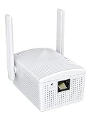
- Connet your wired device to wifi : by using this dual band Ethernet to wireless adapter, your Ethernet-enabled devices can access the Internet via wireless connection, powered by electrical outlet
- Work with any Ethernet enabled devices: This wireless to Ethernet adapter supports smart TV, game console, blu-ray player, network printer, raspberry pi, Ethernet switch or computer etc., no driver installation or update needed
- AC1200 faster wireless speed: up to 867Mbps on 5GHz WiFi or 300Mbps on 2.4GHz WiFi, excellent for online video streaming, gaming, high quality music and facebook by using this 802.11ac WiFi to Ethernet adapter, 4 X speed of N300
- Universal compatibility: This 5GHz universal wireless adapter works with any 802.11ax/ac/a/b/g/n WiFi routers;
- Better WiFi signal: the Ethernet wireless adapter comes with 2X angle adjustable external smart WiFi antennas which pick up stronger WiFi signal than internal ones
For a simple extension of one LAN, both radios operate in bridge mode. If the buildings should be isolated into separate networks, routers can be used instead so the link carries Layer 3 traffic between different subnets.
When a wireless bridge is the right choice
A wireless bridge is useful when the buildings are close enough for a well-engineered radio path, trenching fiber is impractical, and you need more than ordinary Wi-Fi coverage. Common examples include:
- A house and detached office.
- Two buildings on a farm, campus, or business property.
- A warehouse and an office.
- A camera building or gatehouse that needs access to the main network.
- Temporary or semi-permanent buildings where installing cable would be disruptive.
Fiber is generally the better choice when it is practical to install it. A wired link avoids radio interference, does not depend on antenna alignment, and can provide a more predictable path when properly installed. A wireless bridge is not a substitute for fiber when the path is obstructed, the service is mission-critical, or the site requires carrier-grade availability without a properly engineered radio system.
The Tool Desk
Outbyte PC Repair FREEClear out junk files and repair common Windows errorsFree Scan →Outbyte Driver Updater FREEFix the driver behind crashes, sound loss and screen glitchesFind Drivers →Do not proceed solely because you can see one building from the other. Trees, roof parapets, hills, water tanks, cranes, fences, and seasonal vegetation can obstruct the radio path or reduce its performance. If the path is blocked, consider raising the mounting points, moving one radio to a better location, using a relay, or installing fiber.
Plan the radio path before buying equipment
1. Confirm line of sight
Stand at the proposed mounting locations and check whether the radios will have a clear view of one another. Account for the actual height of the radios, not just the height of the buildings. A path that appears clear from ground level may be blocked by a roof edge when the radios are mounted.
For a commercial or long-distance link, use a site survey or a planning tool such as Ubiquiti’s UISP Design Center. A planning tool can help model distance, terrain, antenna height, expected signal level, product compatibility, and the required clearance.
2. Leave room for the Fresnel zone
The radio signal travels through an area around the direct line between the antennas called the Fresnel zone. The center of the zone is especially important. An antenna path can have visual line of sight and still perform badly if trees, fences, roof structures, or terrain intrude into this area.
PC Slower Than It Used to Be?
A free scan shows the junk files, broken settings and background clutter dragging Windows down - then fixes them in one click.Free scan · Windows 10 & 11Crashes, No Sound, or Screen Glitches?
Random freezes, missing sound and display glitches usually trace back to one bad driver. Find and replace yours safely.Free scan · under a minuteAs distance increases, the Fresnel zone becomes larger. Raising the antennas is often the simplest way to clear nearby obstacles. Check the path using the actual distance, terrain, building elevations, and mounting heights. If foliage is close to the path, allow for growth and movement in wind rather than planning around its current position.
3. Estimate capacity rather than relying on advertised speed
Choose the radios based on required throughput, distance, interference, antenna beamwidth, weather exposure, and the amount of traffic from the remote building. Manufacturer range and throughput figures are product-specific, ideal-case references; they are not guaranteed end-to-end performance.
A modern 5 GHz directional pair is often a practical starting point for a short campus link. Longer or more demanding paths may require a narrow-beam outdoor radio, careful channel planning, adequate fade margin, and stronger mounting hardware. A wide-beam indoor access point with a high nominal Wi-Fi speed is not automatically suitable for a building-to-building link.
Also consider traffic direction. A link carrying occasional internet access has different requirements from one carrying security cameras, backups, voice calls, remote desktops, and large file transfers at the same time.
Hardware checklist
| Item | What to look for | Important caution |
|---|---|---|
| Two bridge radios | Outdoor-rated, directional, point-to-point equipment. A matched pair of identical units is the simplest option. | Confirm the exact hardware revision, regional version, supported frequency bands, and bridge features. |
| PoE equipment | Two manufacturer-compatible PoE injectors or a PoE switch that supplies the required voltage and pinout. | Do not substitute a generic injector without checking voltage, wiring, connector, and power requirements. |
| Outdoor Ethernet cable | Shielded, outdoor-rated twisted-pair cable with properly sealed entries and connectors. | Indoor patch cable exposed to sunlight, moisture, or movement can fail prematurely. |
| Surge protection | Ethernet surge protectors suitable for the radio speed and installation, installed and grounded as directed. | Surge protection reduces risk but cannot guarantee survival from a direct lightning strike. |
| Mounting hardware | Rigid poles, brackets, clamps, corrosion-resistant fasteners, and hardware suitable for the wind exposure. | A small amount of movement can change alignment enough to reduce link quality. |
| Grounding and bonding | Grounding conductors and a suitable building grounding point, installed according to the equipment manual and local code. | Low-voltage PoE does not eliminate outdoor lightning and static-discharge hazards. |
| Testing equipment | Laptop, cable tester, spare shielded patch cables, and optionally binoculars or an alignment aid. | Use a controlled throughput test rather than assuming internet speed represents radio capacity. |
For the main equipment, a matched outdoor wireless bridge pair is the appropriate product category. TP-Link’s Pharos guidance recommends a matched pair of identical CPE units for optimal range and performance, while Ubiquiti offers dedicated building-bridge and fixed point-to-point product families. Treat every stated range and throughput figure as a selection reference, not a promise.
For the physical installation, a shielded outdoor Cat6 cable, compatible PoE hardware, Ethernet surge protection, mounting brackets, grounding accessories, and a cable tester are useful additions. Match every accessory to the radio’s speed, connector, power requirements, and grounding method.
Before installation: make the design decisions
Choose Layer 2 bridging or routing
Use a transparent Layer 2 bridge when both buildings should share one subnet and one broadcast domain. The main router or DHCP server can then serve clients in both buildings. This is the simplest arrangement, but broadcast, multicast, and unknown-unicast traffic can also cross the wireless link.
Routing is usually preferable when the buildings need separation. Use different subnets when you want independent DHCP scopes, firewall policies, reduced broadcast traffic, stronger security boundaries, or separate failure domains. In that design, a router at each building or a routing-capable bridge passes Layer 3 traffic between the networks.
Do not enable transparent bridging and router/NAT features on the same devices without understanding the resulting topology. Decide which design you are implementing before connecting the radios to live switches.
Plan management access
Assign each radio a distinct management IP address. The addresses must not conflict with one another or with another device on the LAN. A simple example is:
Building A radio: 192.168.10.20/24
Building B radio: 192.168.10.21/24
Default gateway:  192.168.10.1, if required by the management design
Use addresses appropriate to your existing network. Static management addresses make the radios easier to find after installation. If the equipment supports a dedicated management VLAN, use it instead of exposing the administration interface to ordinary users.
Record the management addresses, radio roles, link identifier or SSID, encryption key, channel, channel width, distance setting, hardware revision, and firmware version. Store the record securely because it contains network-management information.
Quick wins for a faster PC:
Clear out junk files and repair common Windows errorsFree Scan →Fix the driver behind crashes, sound loss and screen glitchesFind Drivers →Also popular on Amazon
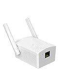
- Convenient Deployment: Your wired device can connect to a WiFi network with this wireless bridge. Eliminates the need for long cable runs in your home to get Internet access.
- Universal Compatibility: With RJ45 port, this WiFi bridge works with any Lan-only devices like smart TV, printer, Blu-ray player, game console, camera, Ethernet switch, desktop, laptop PC, Raspberry Pi, etc.
- Stable Connection: 2 powerful external antennas receives stronger WiFi from router than internal ones. The WiFi to Ethernet adapter brings a reliable connection for a non-WiFi device
- Fast Speed: Working with your 5Ghz WiFi network, the Ethernet bridge delivers a 3 times faster transmission compared with the one which only supports 2.4Ghz WiFi band
- Installation is a Breeze: Pair the Ethernet WiFi adapter with your router via WPS in seconds. WEB UI method allows you to pick other existing Wi-Fi signals and do more settings. Driver setup is not needed
Step-by-step setup
Step 1: Configure both radios indoors
Do the initial configuration on a workbench before climbing onto either building. Connect each radio to its compatible PoE injector or PoE switch, then connect a computer to the injector’s LAN port or the appropriate switch port.
- Identify the exact radio model and hardware revision.
- Install the current firmware intended for that exact model and regional version.
- Change the default administrator username or password immediately.
- Assign distinct management IP addresses.
- Configure the radio roles and wireless link settings.
- Save a written record of the configuration.
Configuring indoors reduces roof work and makes it easier to recover from a wrong setting. Firmware updates and role changes should be completed before physical mounting whenever possible.
Step 2: Configure Building A as the access point or root
Open the radio’s management interface and select the manufacturer’s equivalent of Access Point, Root, or Master. The exact label varies by product.
Configure the following:
- A unique link SSID, device identifier, or point-to-point link name.
- An allowed channel for the radio’s regional version.
- A channel width appropriate to the interference environment.
- The strongest mutually supported link encryption and a long, unique pre-shared key.
- The approximate distance or timing setting if the manufacturer provides one.
- An option that restricts the access point to the intended peer, such as a lock-AP or MAC restriction feature, if supported.
TP-Link’s documented procedure uses Access Point mode, a new SSID, WPA-PSK/WPA2-PSK security, a pre-shared key, and a distance setting. Other manufacturers may use a dedicated point-to-point protocol or different security labels.
What’s actually slowing this PC down?
Pick the symptom - the matching free tool is one click away.
Do not automatically select the widest available channel. A wider channel can increase peak throughput, but it uses more spectrum and may be more susceptible to interference. Start conservatively, inspect the noise environment, and increase channel width only when the measured link and required capacity justify it.
Step 3: Configure Building B as the client or station
On the second radio, select Client, Station, Non-root, or the equivalent peer mode.
- Use the radio’s survey function if one is available.
- Select the Building A link from the scan results.
- Enter the identical security mode and pre-shared key.
- Match the required channel width, radio mode, and distance/timing settings.
- Save the configuration and wait for the station to associate.
The two radios generally need compatible wireless settings. If the station does not associate, verify the role, SSID or link identifier, key, channel, channel width, security mode, firmware compatibility, and distance setting before attempting physical alignment.
Step 4: Connect the radios to the building networks
For a Layer 2 bridge, connect the Building A radio’s Ethernet side to the Building A switch or LAN through the compatible PoE injector. Repeat the arrangement at Building B.
Free tools Windows power users keep installed
One-click scans. No signup required.
Typical connections are:
- Radio Ethernet port to the outdoor-rated cable.
- Outdoor cable through a sealed building entry.
- Indoor cable to the radio’s PoE port on the injector or a compatible PoE switch.
- Injector LAN port to the building switch or router LAN port.
Keep the PoE injectors indoors where practical. Confirm which injector port is labeled PoE and which is labeled LAN before connecting equipment. Never connect a switch or computer to a PoE output unless that device is designed to accept the supplied power.
If the bridge must carry VLANs, confirm that the selected radios support transparent VLAN transport and configure the switch ports deliberately. An untagged access port, tagged trunk, and hybrid port produce different results. Document the native or untagged VLAN on both sides and confirm that spanning-tree behavior is understood.
Step 5: Mount, ground, and weatherproof the radios
Mount each radio on a rigid pole, wall bracket, or structure that will not shift in wind. Use hardware rated for the local weather and corrosion conditions. Aim the radios approximately at one another before tightening the mounts.
For every outdoor cable run:
- Use outdoor-rated, preferably shielded Ethernet cable recommended by the equipment manufacturer.
- Seal cable connectors and entry points according to the radio instructions.
- Leave a drip loop so water does not run directly into the radio or building entry.
- Avoid sharp bends and avoid allowing the cable’s weight to hang from the radio connector.
- Keep the cable route away from avoidable sources of electrical interference.
Bond and ground the radio, mast, shielded cable, surge protector, and PoE installation according to the manufacturer’s instructions and applicable electrical code. Use a suitable building grounding point. Grounding through a shielded cable and a grounded PoE system must be done as specified by the equipment documentation; do not improvise a path to a random pipe or other object.
Rooftop and tower work has serious fall and electrical hazards. Use qualified personnel for roof, tower, electrical, and lightning-protection work. Follow the applicable fall-protection requirements for roof edges, openings, ladders, towers, and elevated platforms, and stop work during hazardous weather.
Step 6: Align the antennas precisely
Power both radios and open their link-status pages. Useful measurements may include received signal level, noise floor, signal-to-noise ratio, modulation rate, retransmissions, error counts, and overall link quality.
- Loosen the mount enough to make small, controlled adjustments.
- Adjust the horizontal direction of one radio in small increments.
- Allow the status readings to settle after each movement.
- Repeat the process vertically.
- Fine-tune the other radio if necessary.
- Tighten the hardware without allowing the radio to move.
- Recheck the readings after tightening.
Do not optimize for signal strength alone. A strong signal can still perform poorly if the noise floor is high, the channel is congested, the antennas are cross-polarized, the cable or PoE path is faulty, or the radios are too close and overdriving their receivers. Look for a healthy signal-to-noise ratio, stable modulation, low retransmission rates, and consistent throughput.
Step 7: Verify the link from the radio outward
Test in layers so a failed result identifies a smaller part of the system:
Do these 3 things before closing this tab:
1Clear out junk files and repair common Windows errors2Fix the driver behind crashes, sound loss and screen glitches3Repair Windows errors before they cause bigger problems- Confirm that both radios power up.
- Confirm the expected firmware and management IP addresses.
- Confirm that the station associates with the access point or root.
- From Building A, ping the Building A radio.
- From Building A, ping the Building B radio across the link.
- Ping a device connected to the opposite building’s switch.
- Confirm DHCP, DNS, default-gateway access, and any required VLANs.
- Run a controlled throughput test in both directions.
- Test the applications that motivated the installation, such as file access, cameras, VoIP, or remote desktop.
- Monitor the link during busy radio periods and, where practical, representative weather conditions.
For an IP connectivity check, a computer on Building A might run:
Also popular on Amazon
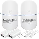
- READY TO USE BUNDLE: A set of two NanoStation Loco 5 AC devices, meticulously PRE-PROGRAMMED to function as a Point-to-Point Wireless Bridge.
- BUNDLE INCLUDES: 2 Paired airMAX NanoStation 5 AC Loco (Ubiquiti), 2 POE Injectors with Power Cords, 2 Straps, Installation Guide.
- HIGH-SPEED CONNECTIVITY: The AirMAax LOCO 5AC works in the 5GHz frequency band and delivers over 450 Mbps throughput for fast and reliable data transmission.
- MULTIPLE APPLICATIONS: Ideal for expanding network coverage between buildings, linking distant sites, or offering broad-area wireless internet connectivity.
- LONG-RANGE CAPABILITIES: Perfect for Point-to-Point and Point-to-Multipoint setups, enabling connectivity over long distances.
ping 192.168.10.21For a more meaningful capacity test, place a test computer on each side and use a tool such as iperf3. Run iperf3 -s on one side and iperf3 -c <server-address> on the other, then repeat with the reverse direction option. Test traffic should not disrupt production users.
An internet speed test measures the internet connection as well as the bridge. It cannot by itself tell you the capacity of the wireless hop. A local, two-sided test is more useful for evaluating the bridge.
Independent reader supportYour contribution helps us test, update, and keep practical guides available for everyone.Layer 2 bridge versus routed link
| Design | Use it when | Advantages | Trade-offs |
|---|---|---|---|
| Transparent Layer 2 bridge | Both buildings should operate as one LAN or share a subnet. | Simple addressing; one DHCP service can serve both sides; devices can discover one another normally. | Broadcasts, multicast, unknown unicast, spanning-tree traffic, and network faults can cross the radio link. |
| Routed Layer 3 link | Buildings need separate subnets, security boundaries, or independent DHCP and firewall policies. | Better isolation and control; less broadcast traffic; failures can be contained more effectively. | Requires routing, firewall rules, DHCP relay or a local DHCP service, and application planning. |
In either design, do not create a physical or logical loop accidentally. If two links connect the same switches, or if a bridge joins parts of the same switching topology more than once, spanning tree or another deliberate loop-prevention design is essential.
U.S. regulatory considerations
In the United States, operate the radio only within the bands, power levels, antenna combinations, and operating modes allowed by the device’s FCC authorization and current FCC rules. The exact regional version of the hardware matters.
FCC Part 15 rules distinguish fixed point-to-point operation from point-to-multipoint and omnidirectional operation. For the 5.725–5.850 GHz U-NII band, the applicable rule includes conditions for fixed point-to-point devices using directional antennas above 6 dBi, with additional power-reduction requirements above 23 dBi. Those figures do not authorize every radio, antenna, channel, or installation; the operator or professional installer must verify the complete combination.
Do not assume that a product labeled 5 GHz is legal outdoors on every channel in every country. One Ubiquiti product guide, for example, lists different U.S. and Canada U-NII sub-bands for a particular model. Some 5 GHz channels may also require radar detection and dynamic-frequency-selection behavior.
Outside the United States, check the rules of the national spectrum regulator. In any country, also check landlord permission, building-management requirements, aviation or tower considerations, local electrical code, and restrictions on roof penetrations or external equipment.
Do these 3 things before closing this tab:
1Fix the driver behind crashes, sound loss and screen glitches2Repair Windows errors before they cause bigger problems3Scan for outdated or missing drivers - takes under a minuteTroubleshooting guide
| Symptom | Likely causes | What to check or change |
|---|---|---|
| Radios do not associate | Wrong role, credentials, channel, radio mode, distance setting, or alignment. | Confirm one unit is AP/root and the other is client/station. Match SSID, security, key, channel, width, radio mode, and distance. Check that the station is not locked to another access point. Verify antenna choice and alignment. |
| Link associates but is slow | Interference, low signal-to-noise ratio, retransmissions, poor modulation, bad cable, unstable PoE, or excessive channel width. | Inspect noise, channel use, modulation, error counters, and Ethernet negotiation. Realign the antennas, reduce channel width, select a cleaner permitted channel, improve Fresnel clearance, and test each Ethernet segment locally. |
| Link drops in wind or rain | Moving mount, loose clamps, water ingress, poor cable sealing, marginal fade margin, or vegetation in the path. | Inspect the mount and seals, check for movement, recheck alignment after weather exposure, and reassess the path. Use a more suitable radio pair, raise the mount, shorten the link, or install a wired alternative if the margin remains poor. |
| Far-side devices cannot obtain DHCP | Layer 2 and routed designs mixed together, incorrect VLAN tagging, switch-port mode, spanning-tree behavior, or blocked DHCP traffic. | First identify the intended design. For Layer 2, check VLAN tags, switch modes, spanning tree, and DHCP reachability. For routed networks, check the remote subnet, routes, firewall rules, and DHCP relay. |
| Radios become unreachable after installation | Duplicate IP address, incorrect management subnet or VLAN, wrong injector connection, or management isolation. | Check both management addresses, local switch ports, PoE injector LAN connections, VLAN placement, and whether the management interface is intentionally isolated from users. |
| Equipment appears damaged after a storm | Surge or lightning damage to the radio, cable, injector, or switch. | Disconnect power safely. Inspect surge protectors, PoE injectors, cable shields, and grounding conductors. Replace damaged parts instead of repeatedly powering questionable equipment. |
Use the failure location to narrow the diagnosis
- No power: check the outlet, PoE injector, cable continuity, connector seating, and required voltage.
- Power but no management page: check the computer’s subnet, duplicate IP addresses, switch port, and management VLAN.
- Management works but no wireless association: check radio roles, link credentials, channel settings, and alignment.
- Wireless association works but remote LAN devices fail: check bridge mode, switch ports, VLAN tags, DHCP, firewall rules, and spanning tree.
- Ping works but applications fail: check application ports, MTU or VLAN behavior, latency, packet loss, multicast requirements, and the application’s own configuration.
Common mistakes to avoid
- Using two ordinary indoor access points or Wi-Fi repeaters instead of purpose-built outdoor directional bridge radios.
- Choosing equipment based only on the advertised range or maximum wireless speed.
- Ignoring the Fresnel zone because the buildings are visually visible.
- Using different or incompatible radio families without verifying that their modes and security settings interoperate.
- Selecting the widest channel automatically in a congested area.
- Giving both radios the same management IP address.
- Connecting a PoE injector backward or using one with the wrong voltage or pinout.
- Running unshielded indoor cable outdoors or leaving cable entries unsealed.
- Skipping surge protection, bonding, and grounding.
- Mounting a radio on a flexible pole or bracket that moves in the wind.
- Testing only internet speed instead of measuring the local wireless hop.
- Extending a flat LAN across the bridge without considering broadcasts, multicast, VLANs, spanning tree, and failure isolation.
- Assuming every 5 GHz channel is legal for outdoor use in every region.
- Climbing onto a roof without the appropriate fall protection, weather assessment, and electrical precautions.
When to hire a professional
Professional help is especially sensible when the path is obstructed, the radios will be installed on a tall building or tower, the link supports business-critical services, grounding or lightning protection is unfamiliar, or the installation requires roof penetrations or electrical work.
A professional wireless site survey can confirm the path, Fresnel clearance, interference environment, antenna height, expected signal level, and capacity before hardware is purchased. A qualified installer can also handle mounting, cable routing, grounding, surge protection, alignment, and safe elevated work. Ask for the proposed radio model, regional authorization, expected throughput, fade margin, grounding method, and acceptance-test procedure rather than accepting a range claim alone.
Optional use cases after the link is stable
Once the bridge has passed local throughput, packet-loss, VLAN, and application tests, it can transport traffic for remote cameras, production equipment, phones, workstations, or file systems. A cloud video service may be useful for a separate camera or production workflow, but it is not required to install or validate the bridge. Always test the network transport first; an application service cannot compensate for poor alignment, interference, bad cabling, or insufficient capacity.
Frequently Asked Questions
Can I use two Wi-Fi routers to create a wireless bridge?
Only if the specific routers support a compatible wireless bridge or point-to-point mode. Ordinary router, repeater, or mesh modes may introduce NAT, reduce throughput, or fail to provide a transparent Ethernet connection. Purpose-built outdoor directional bridge radios are the safer choice for two-building links.
Do both buildings need to use the same subnet?
No. A transparent Layer 2 bridge normally places both buildings on the same subnet, while a routed design uses different subnets and passes Layer 3 traffic between them. Routing is preferable when the buildings need isolation, separate DHCP, or separate firewall policies.
How far can a wireless bridge reach?
There is no universal distance. The usable range depends on the exact radio and antenna, regional power limits, line of sight, Fresnel clearance, interference, channel width, weather margin, mounting stability, and required throughput. Manufacturer range figures should be treated as planning references, not guaranteed results.
Will rain or wind interrupt the connection?
A properly selected and aligned outdoor link can be designed to tolerate normal weather, but a marginal link may drop during rain or when wind moves the antennas. Rigid mounting, sealed cabling, adequate fade margin, and a clear path are important. If the link remains unreliable, reassess the radio design or use fiber.
Can the bridge carry VLANs?
It can if the selected radios support transparent VLAN transport and the switch ports and radio settings are configured consistently. Confirm tagged and untagged VLAN behavior in the exact product documentation before deploying the link.
The Bottom Line
The dependable method is straightforward: use two compatible outdoor directional radios, configure one as the AP/root and the other as the client/station, give them unique management addresses, connect them through correct PoE equipment, mount and ground them properly, clear the Fresnel zone, align them using link metrics, and test the complete path in both directions. If the path is obstructed, the installation is safety-critical, or the link must be exceptionally reliable, get a site survey or choose fiber instead.

