
A 32.768 kHz crystal is a passive resonator, not a clock source you can connect to a GPIO. For an RTC, low-power timer or wake-up clock, connect a compatible fundamental-mode crystal to the MCU or RTC’s dedicated low-frequency oscillator pins. The chip supplies the amplifier, and the crystal-load network must match that specific device.
The exact schematic, capacitor values and firmware registers depend on the MCU or RTC part number. Until that is known, use the reference design and calculations below as a safe design framework—not as a universal drop-in circuit.
First decide what “32.768 kHz oscillator” means
These four implementations are different:
| Need | Best architecture | Main trade-off |
|---|---|---|
| RTC timekeeping, low-power wake-ups or an asynchronous timer | MCU low-frequency oscillator with a 32.768 kHz crystal | Lowest component count and power, but startup and layout are device-sensitive |
| Calendar, alarms, battery backup and a simple digital interface | Dedicated RTC IC with its specified crystal | Extra IC, but simpler timekeeping firmware |
| A guaranteed logic-level clock for another input | Complete 32.768 kHz oscillator module | Higher current and cost; check voltage, output drive and tolerance |
| A discrete experiment without an MCU oscillator | CMOS-inverter Pierce oscillator | Requires gain, bias, negative-resistance and drive-level analysis; not the beginner default |
A bare crystal cannot produce a usable square wave by itself. An oscillator module’s output must go to a digital input or clock pin; it must not be wired to a crystal-output pin unless the device explicitly supports external-clock bypass mode.
Reference crystal connections
MCU or RTC with two oscillator pins and external loading
MCU/RTC OSC32_IN  ──────┬──── Y1, 32.768 kHz ────┬──── OSC32_OUT
                        │                          │
                       C1                         C2
                        │                          │
                       GND                        GND
Place Y1, C1 and C2 beside the oscillator pins. Use this topology only when the selected IC’s reference circuit calls for two external capacitors.
What’s actually slowing this PC down?
Pick the symptom - the matching free tool is one click away.
#1 Best Overall
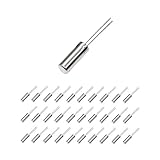
- This is an 32.768 KHz 32768HZ Crystal Oscillator 2 x 6 mm
- Widely used in TV , automobile electronics , pc cards , electronical meter , DVD , MP3 , etc.
- Size(Each One) : 2 x 6 mm/ 0.08" x 0.24"(D*H);
- Package Included:30 Pcs A32.768 KHz 32768HZ Crystal Oscillator 2 x 6 mm(If the number of products received is incorrect, please contact us . we will refund or give you a replacement)
- We highly appreciate all customers opinions to improve the selling, also if anything you unsatisfied, please contact us for probable best solution.
Device with internal load capacitance
MCU TOSC1 / OSC32_IN ───────── Y1, 32.768 kHz ───────── MCU TOSC2 / OSC32_OUT
Configure the internal loading if the datasheet provides it. Do not add capacitors merely because a different MCU uses 22 pF parts. Microchip documents cases where internal capacitance and board parasitics satisfy the crystal requirement: AVR recommended capacitor guidance.
Complete oscillator module
VCC ───────── oscillator VDD
GND ───────── oscillator GND
oscillator OUT ───── MCU timer/clock input
Verify the module’s supply range, logic thresholds, duty cycle, startup time, frequency tolerance, temperature stability, standby behavior and pinout.
Select a compatible crystal
- Nominal frequency: 32.768 kHz.
- Fundamental-mode, parallel-resonant type unless the IC datasheet says otherwise.
- Specified load capacitance, commonly 6 pF, 7 pF, 9 pF or 12.5 pF.
- Equivalent series resistance (ESR) within the oscillator’s permitted range.
- Maximum drive level compatible with the low-power oscillator.
- Frequency tolerance, temperature coefficient and aging appropriate to the timekeeping requirement.
- Package and footprint that match the PCB land pattern.
Microchip’s AN2648 crystal-selection application note explains ESR, load capacitance, negative resistance, stability and testing for AVR oscillators. A correct frequency marking alone does not establish compatibility.
Rank #2

- Frequency: 32.768KHz; Frequency Tolerance : ±20ppm
- Mounting Type: DIP; Number of Pins: 2
- Body Size: 2 x 6mm / 0.08" x 0.24" (D*L)
- DIP Quartz Crystal Oscillators for RISC & CISC Microcontrollers
- Widely used in TV, electronics, PC cards, electronical meter, DVD, MP3, MP4, etc
Calculate the load capacitors
For two external capacitors, the crystal’s effective load is approximately:
Recommended Free Tools
CL ≈ (C1C2)/(C1 + C2) + Cstray
With equal capacitors:
CL ≈ C/2 + Cstray
So a first estimate is:
C ≈ 2(CL − Cstray)
Some Microchip families express the same design as:
CEXT = 2 × (Ccrystal − Cinternal − CPCB)
See the manufacturer’s load-capacitance example for the device-specific interpretation.
Rank #3

- 30Pcs 32.768KHz 32.768 KHZ 32768HZ 32.768K Crystal Oscillator 2 x 6 mm 2*6mm
- Size: 2*6mm
Worked example
Assume a 12.5 pF crystal, 1.7 pF of MCU internal capacitance and 0.5 pF estimated board contribution per side:
CEXT = 2(12.5 − 1.7 − 0.5) ≈ 20.6 pF
A nearby standard value such as 20 pF or 22 pF may be appropriate only if the selected IC permits it. Excess capacitance can stop startup, increase current and pull the frequency away from nominal. Validate the result on the final PCB; never apply a universal “22 pF rule.”
Free tools Windows power users keep installed
One-click scans. No signup required.
PCB layout that gives the oscillator a chance to start
- Put the crystal immediately beside the MCU or RTC oscillator pins.
- Keep both crystal traces short, direct and approximately symmetric.
- Avoid vias in the crystal-node traces where possible.
- Place each load capacitor at its corresponding pin, with a short, quiet ground return.
- Keep switching-regulator inductors, switch nodes, USB or high-speed clocks, LEDs and long GPIO traces away from the network.
- Keep oscillator-node copper small; avoid large pours and unnecessary stubs.
- Do not attach a normal oscilloscope test point directly to a high-impedance crystal node.
- Remove flux residue and prevent moisture or contamination around the crystal.
Follow the selected manufacturer’s reference layout. Microchip’s CEC1712 layout guide and CEC1702 layout guide describe parasitic-control and low-power layout concerns. TI gives additional placement guidance in its CC31 PCB layout document.
Rank #4

- PRECISION FREQUENCY: High-quality 32.768KHz crystal oscillator designed for accurate timekeeping and clock applications
- PACKAGE CONTENTS: Set includes 20 pieces of silver clock crystals, providing excellent value for multiple projects
- COMPACT SIZE: Each crystal measures 3mm x 8mm, making them ideal for space-constrained electronic applications
- COMPATIBILITY: Perfect for electronic circuits, microcontrollers, real-time clocks, and other timing-sensitive devices
- CONSTRUCTION: Passive component design with reliable crystal structure ensures stable frequency output
Firmware: configure the low-frequency clock, then wait for synchronization
Register names differ across classic AVR, tinyAVR, megaAVR 0-series, AVR Dx and STM32 families. The snippets below are templates, not universal compile-ready programs.
AVR-style asynchronous timer template
#include <avr/io.h>
#include <avr/interrupt.h>
#include <stdint.h>

volatile uint32_t seconds;

ISR(TIMER2_COMPA_vect) {
    seconds++;
}

static void rtc_oscillator_init(void) {
    /* Replace every register and bit with the named AVR's datasheet values. */
    ASSR |= (1 << AS2);          /* asynchronous Timer2 example */
    TCCR2A = (1 << WGM21);       /* CTC */
    TCCR2B = (1 << CS22) | (1 << CS20);
    OCR2A = 127;                  /* example only */
    TIMSK2 |= (1 << OCIE2A);

    while (ASSR & ((1 << TCN2UB) | (1 << OCR2AUB) |
                   (1 << TCR2AUB) | (1 << TCR2BUB))) { }
    sei();
}
Choose the prescaler N and compare value from the actual timer:
ftimer = 32,768/N
For a 1 Hz tick, include the timer’s off-by-one rule and wait for every clock-synchronization-busy flag before using the peripheral. Microchip describes the AVR RTC/asynchronous-timer concept in its AVR RTC documentation.
Best Value
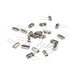
- High Precision & Stability: 32.768MHz frequency with ±30ppm tolerance ensures accurate and stable performance for various electronic applications.
- Wide Compatibility: Standard 49S through-hole (THT) design fits most PCB boards, ideal for DIY projects, clocks, microcontrollers, and industrial devices.
- Reliable Load Capacitance: 20pF load capacitance ensures compatibility with common circuit designs, reducing signal interference.
- Durable & Lead-Free: Made with high-quality quartz and lead-free materials, offering long-term durability and RoHS compliance.
- Cost-Effective Pack: Includes 20 pieces per order, perfect for bulk needs, replacements, or prototyping without frequent reordering.
STM32 LSE/HAL template
RCC_OscInitTypeDef osc = {0};
RCC_PeriphCLKInitTypeDef clk = {0};

osc.OscillatorType = RCC_OSCILLATORTYPE_LSE;
osc.LSEState = RCC_LSE_ON;
osc.PLL.PLLState = RCC_PLL_NONE;
if (HAL_RCC_OscConfig(&osc) != HAL_OK) Error_Handler();

clk.PeriphClockSelection = RCC_PERIPHCLK_RTC;
clk.RTCClockSelection = RCC_RTCCLKSOURCE_LSE;
if (HAL_RCCEx_PeriphCLKConfig(&clk) != HAL_OK) Error_Handler();
STM32 families vary in LSE drive strength, backup-domain reset rules, pin names, clock-selection registers and HAL order. Select the exact STM32 part before turning this template into buildable code.
Independent reader supportYour contribution helps us test, update, and keep practical guides available for everyone.Verify the circuit without killing the oscillation
- Check the schematic against the exact MCU or RTC datasheet, including pin multiplexing and backup-domain power.
- Confirm the crystal frequency, load rating, ESR, drive rating and footprint.
- Power the board and allow the specified startup interval.
- Read the oscillator-ready or clock-status flag before enabling dependent peripherals.
- Verify a 1 Hz RTC/timer tick, or route a divided clock through an approved clock-output function.
- For frequency measurement, use timer capture, an RTC square-wave output, a clock-output pin or a suitable active probe. A standard oscilloscope probe can add enough capacitance to stop or detune the crystal.
- Compare elapsed time with a reference over hours; use multi-day testing when accuracy matters.
- Repeat tests through reset, brownout, sleep and battery switchover.
Microchip’s AN2648 PDF covers practical selection and testing considerations.
Troubleshoot by symptom
No oscillation or no ready flag
- Verify the exact oscillator pins and that firmware has not changed them to GPIO.
- Check crystal ESR and load capacitance against the oscillator limits.
- Try the manufacturer’s recommended capacitor values and permitted drive setting.
- Inspect solder joints, footprint orientation and board cleanliness.
- Remove nearby switching activity and compare the layout with the reference design.
- Confirm backup-domain supply, clock enable and reset sequencing.
Clock is fast or slow
Check effective load capacitance, crystal tolerance, temperature coefficient, aging and board parasitics. Crystal frequency is strongly load-dependent; Microchip explains this in its XTAL32K connection guidance. Apply the MCU or RTC calibration mechanism only after confirming the hardware load.
Works on a breadboard but not on the PCB
The two assemblies have different parasitic capacitance, leakage, trace length and noise coupling. Treat the final PCB—not the breadboard—as the valid design and inspect vias, asymmetry, contamination and nearby switching nodes.
Works but current is excessive
Check unnecessarily high drive strength, excessive capacitor values, out-of-range ESR and failure to enter the intended sleep mode. A passive crystal can consume far less than an active module, but current figures are device-specific; one Microchip example specifies hundreds of nanoamps only under stated crystal and ESR conditions. See its oscillator characteristics.
Information required for an exact schematic and working program
To turn this reference into a pin-accurate design, specify:
Quick Recap
- Exact MCU or RTC part number and package.
- Supply voltage and whether a separate backup supply is used.
- Crystal manufacturer and part number, including load capacitance and ESR.
- Whether the 32.768 kHz signal must leave the board or only clock an internal RTC/timer.
- Accuracy target, temperature range and calibration requirement.
- PCB technology, crystal package and CAD tool.
- Firmware platform and compiler, such as bare-metal AVR, STM32 HAL/LL, Zephyr or ESP-IDF.
Product prices and availability are accurate as of the date/time indicated and are subject to change. Any price and availability information displayed on Amazon at the time of purchase will apply.

