
Recommended Free Tools
An Arduino can control a suitable brushed, series-wound universal motor by timing a power triac’s firing point within each AC half-cycle. This is phase-angle control: it changes the effective voltage applied to the motor. It is not ordinary, free-running Arduino PWM, and it is not a ready-to-wire design for 220/230 VAC. The Arduino Project Hub example names an MST_K07_CL motor-control module, but does not establish that its circuit is safe or suitable for your motor and installation.
What “universal motor” means here
This method applies to the brushed, series-wound motor type called a universal motor—not to AC motors generally. NXP describes a universal motor as a series-wound DC motor that can operate from AC. The motor’s type matters: a generic AC motor, induction motor, or electronically controlled appliance motor should not be assumed compatible with a universal-motor controller.
The phrase “washing machine” appears in the title of the 2018 Arduino Project Hub example, but that does not establish that every washing-machine motor is a suitable load. Identify the motor and consult its documentation before choosing a controller.
How Arduino phase-angle control works
A controller needs a reference point in the AC waveform, typically a zero-crossing signal, and a timer. After each zero crossing, the microcontroller waits for a chosen delay and triggers a power triac. Triggering earlier or later changes how much of that half-cycle reaches the motor. A triac continues conducting until the load current falls below its holding current, usually around the AC waveform’s current zero.
#1 Best Overall

- L298N Motor Driver Controller Board Module: L298N as main chip. Can drive one 2-phase stepper motor, one 4-phase stepper motor or two DC motors
- Operating mode: H-bridge driver (dual)
- Logic voltage: 5V(current 0mA-36mA)
- Drive voltage: 5V-35V(current: 2A (MAX single bridge)
- Maximum power: 25W
NXP’s Motor Power Control Tutorial describes the zero-cross reference and timer approach. The exact detector, isolation arrangement, timing, and power stage depend on the design and line frequency; these principles are not a complete mains wiring schematic.
Random-phase and zero-cross optotriacs are not interchangeable
For selectable firing angles, the optotriac driver must allow triggering at a chosen point in the waveform. ON Semiconductor’s AN-3006, Optically Isolated Phase Controlling Circuit Solution distinguishes random-phase devices from zero-cross types. Its examples include MOC301X, MOC302X, and MOC305X random-phase families, and MOC316X and MOC308X zero-cross families; it uses an MOC3023 in its phase-control example. These are examples in an application note, not universal part recommendations.
Rank #2

- Working voltage: DC 5V-36V, the trigger source: digital high-low (DC 3.3V - 20V), continuous current: 15A, maximum current and power: 30A, 400W, operating Temperature: -40-85℃, size: 1.34x0.67x0.47inch/34 x 17 x12mm (length x width x height)
- DUAL MOS DRIVE: The MOSFET motor board Utilizes dual MOS parallel connection with active output, featuring lower internal resistance, higher current, and robust power output (15A, 400W at room temperature), meeting the requirements of most devices
- WIDE VOLTAGE RANGE, PWM SUPPORT: With a working voltage range of DC 5V to 36V and compatibility with PWM signals, this PWM regulator control panel offers versatility in controlling devices. It accepts digital signals within the voltage range of DC 3.3V to 20V, making it suitable for use with micro controller IO ports, PLC interfaces, and other DC power sources
- COMPACT DESIGN, EASY INTEGRATION: Measuring just in 34x17x12mm (1.34x0.67x0.47inch), this high power PWM MOSFET driver module offers a compact form factor, facilitating effortless integration into various applications. Easily achieve control over high-power devices with this versatile and efficient module
- WIDELY APPLICATIONS: The MOSFET switch drive module is a versatile power control module that excels in a wide range of applications. Its design allows for precise control of high-power devices such as motors, LED lights, bulbs, micro-pumps, and solenoid valves. By accepting PWM signals, it can accurately regulate motor speeds, adjust lamp brightness, and more
A zero-cross optotriac is designed to switch near the waveform’s zero point. That is useful for near-zero switching, but it does not provide arbitrary phase-angle selection. Ordinary Arduino PWM likewise does not substitute for synchronizing triac firing to the mains waveform.
What the Arduino Project Hub example establishes
The Arduino Project Hub page, “Control a 220VAC Universal AC Motor with Arduino”, was published September 9, 2018. It describes sending commands to switch a motor on or off and set a 0–100 speed value. That range describes the project’s command, not measured RPM or a verified speed range.
Rank #3
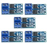
- Operating Voltage: DC 5V - 36V; The trigger source: digital high-low (DC3.3V - 20V); continuous current: 15A, enhance cooling conditions, the maximum current up to 30A; power: 400W.
- High Reliability, High Availability: It adopts double MOS parallel active output to show lower internal resistance,greater electric current and power. Besides it works at 15A,400W under common temperature which satisfies most devices usage and realizes the control of great power devices in a relaxed way.
- Supporting Multiple Signal Source Triggers: Can be connected microcontroller IO port, PLC interfaces, DC power, etc.
- PERFECT SUPPORT PWM: You can access the PWM signal, the signal frequency 0--20KHZ perfect support.
- WIDELY APPLICATIONS:You can control the output of power equipment, motors, light bulbs, LED lights, DC motors, micro-pumps, solenoid valves, etc., can input PWM, control motor speed, lamp brightness and so on.
The project lists an Arduino Mega 2560 Rev3, an MST_K07_CL universal AC motor torque-control module, a PC817 optoisolator, 4.75 kΩ and 10 kΩ resistors, and a 10 µF capacitor. It says another board, such as a Nano, may be used. The page is a community project description; it does not independently validate the circuit, document measured performance or speed feedback, or establish current module stock, certification, or suitability for a particular motor.
Why the 115 VAC example is not a 220/230 VAC build guide
ON Semiconductor’s AN-3006 explains phase control and illustrates an isolated circuit, but its worked circuit targets a 115 VAC load and an induction motor. The note also discusses universal-motor use; that does not make the illustrated component values a validated 220/230 VAC design. Do not transplant them to a different line voltage or motor.
Rank #4

- Adjustable duty cycle: 0%-100%
- Maximum output power: 30W
- Maximum continuous output current: 2A
- Input voltage: DC 2.2V-15V; output voltage: 1.8V-15V
- Equipped with a 2A self-recovery fuse, which will automatically disconnect if the current is too large, and will automatically recover after the fuse cools down
A 220/230 VAC design must be assessed for its actual supply and load, including component ratings, insulation, board layout, protection, heat dissipation, enclosure, and applicable local electrical requirements. NXP discusses a possible non-isolated arrangement in which the MCU ground is connected to the AC line, while noting that isolation may be needed for safety or noise susceptibility. A line-referenced Arduino is not a casual hobby wiring approach. The word “opto” alone does not prove that an assembled circuit has an adequate isolation boundary.
How to evaluate the MST_K07_CL or another controller
“MST_K07_CL universal AC motor controller module” is the specific search phrase supported by the project page, not confirmation of a current product listing. Before considering any module, obtain current manufacturer or seller documentation and check the actual application against it.
Outdated Drivers Are Slowing You Down
One free scan finds every outdated or missing driver and matches the right update for your exact hardware.Free scan · exact hardware matchWindows Errors? Fix Them Before They Spread
Repair common Windows errors and clear accumulated junk for a smoother, more stable PC - no reinstall needed.Free scan · no reinstallBest Value

- DROK DC motor driver input voltage range is DC 6.5V-27V, can be input DC 12V or 24V, rated output current of each port is 7A, total output power is 160W.
- STRONG DRIVE: the motor controller board adopts dual H bridge, can drive two DC motors at the same time.
- FORWARD and REVSERSELY ROTATE: the IN1, IN2/IN3, IN4 port can control forward or reverse motor rotation.
- PWM SPEED CONTROL: enable signal terminal (ENA) input PWM can regulate speed, PWM frequency range 0-10KHZ.
- UNDER VOLTAGE PROTECTION: the motor driver module is with under voltage protection to prevent instantaneous large current from damaging the module.
- Input voltage: Does the documentation explicitly cover your supply, including 220/230 VAC where applicable?
- Load type: Is the controller specified for the motor type you have, rather than only for a generic resistive load or another motor?
- Current and thermal limits: Are ratings documented for the motor’s operating and startup conditions, and for the required cooling and enclosure?
- Control method: Does it support random-phase firing when phase-angle control is required, rather than only zero-cross switching?
- Isolation and protection: Does the documentation describe the isolation boundary and required protective components for the complete installation?
- Speed feedback: Does the system measure motor speed, or merely accept a command value? A command setting alone does not establish closed-loop RPM control.
The available sources do not provide comparable ratings for the MST_K07_CL and alternative modules, so they do not support a product-to-product performance comparison.
Independent reader supportYour contribution helps us test, update, and keep practical guides available for everyone.Open-loop commands versus actual speed regulation
The Project Hub example documents a 0–100 command, but does not document feedback measurement for that Arduino setup. Treat such a value as a requested control setting unless the controller’s documentation specifies otherwise. To claim or maintain a target RPM, a system needs a suitable speed sensor, a feedback-control method, and a controller designed for the motor and operating conditions; the cited project description does not establish those features.
When to use a documented commercial controller
For a production machine, unattended operation, high-power tool, or safety-critical application, use a properly rated and documented commercial controller and have the actual installation assessed by a qualified person. Neither a published Arduino project nor an illustrative application-note circuit certifies a build for your motor, supply, enclosure, or jurisdiction.
Additional manufacturer context is available in NXP’s Motor Power Control Tutorial and Texas Instruments’ Low Cost AC Motor Control Design Based on MSPM0 and Triac. The TI design concerns a different microcontroller implementation and does not validate the Arduino example or MST_K07_CL module.
Free tools Windows power users keep installed
One-click scans. No signup required.
Quick Recap
Product prices and availability are accurate as of the date/time indicated and are subject to change. Any price and availability information displayed on Amazon at the time of purchase will apply.

