
PC Slower Than It Used to Be?
A free scan shows the junk files, broken settings and background clutter dragging Windows down - then fixes them in one click.Free scan · Windows 10 & 11Crashes, No Sound, or Screen Glitches?
Random freezes, missing sound and display glitches usually trace back to one bad driver. Find and replace yours safely.Free scan · under a minuteReliable isoSPI starts with the right topology, a properly terminated twisted pair, suitable isolation components, and careful physical layout. The LTC6811-1 supports a point-to-point daisy chain; the LTC6811-2 supports addressed devices on a shared pair. Neither topology is inherently “bullet-proof”: the harness and battery-pack environment must be validated for the specific design.
How isoSPI carries data across an isolated battery system
isoSPI transports SPI data over a differential two-wire link. Pulse transformers provide galvanic isolation between the communicating domains and help reject common-mode interference on the wiring. The LTC6811 family integrates isoSPI for communication among floating battery-monitor modules; an LTC6820 can convert a host microcontroller’s conventional SPI signals to isoSPI at the host boundary when that SPI domain needs isolation from the battery stack.
Isolation is only as suitable as the components and barrier design. Select pulse transformers for the battery stack’s actual working voltage and insulation requirements. A transformer’s one-second hipot test rating is not the same as its continuous working-voltage rating; confirm the latter in the transformer manufacturer’s data.
Choose daisy-chain or addressable multi-drop deliberately
The LTC6811-1 and LTC6811-2 use different network topologies. The choice affects wiring, stubs, and communication timing, so make it as part of the system design rather than as a late firmware decision.
#1 Best Overall
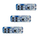
- The power range described is applicable to the following products: vacuum cleaner, massager battery pack, LED light backup power supply, 12V electronic products, solar street light battery pack, monitoring standby power supply, etc.
- With overcharge, over discharge, over current, short circuit and other protection functions, for a variety of shapes of various shapes 3.7V lithium battery.
- High quality MOSFETs such as VISHAY, AOS, IR, etc., FR-4 low temperature coefficient sheet, well designed and tested.
- It is small in size and suitable for many applications requiring high integration and low cost. It can meet various performance requirements and ensure the absolute safety and reliability of the battery pack.
- This protection board can not be used for iron ion polymer battery, hand drill battery pack, electric fish battery pack, electric bicycle battery pack, 2 pieces and 24V series, 775 (4A) or above motor, 1W fisheye LED lamp.
| Design consideration | LTC6811-1 daisy chain | LTC6811-2 addressable multi-drop |
|---|---|---|
| Topology | Point-to-point hops connect devices in a chain, with one host connection. | Addressed devices share a pair. |
| Wiring | Requires links between successive monitor modules. | Can reduce host wiring by sharing the pair among addressed devices. |
| Stubs | Each hop is point-to-point rather than a shared bus with device stubs. | Keep multi-drop stubs short; added capacitance can distort pulses. |
| Timing and data latency | Network size and wire length affect timing and data latency. | Network size and wire length affect timing and data latency; account for the shared network when setting communication timing. |
| Fault containment, EMC exposure, and serviceability | Not stated in the cited Analog Devices product information as universal comparative outcomes; evaluate these in the actual pack and harness. | Not stated in the cited Analog Devices product information as universal comparative outcomes; evaluate these in the actual pack and harness. |
The topology labels do not guarantee a particular fault response, EMC result, or service procedure. Those depend on the full implementation, including harness routing, connectors, module count, and operating conditions.
Design the interconnect as part of the signal path
Use the specified twisted pair, terminate the link at the master and far end, and account for both cable length and the number of devices when setting serial timing. On a shared addressable pair, keep stubs short: their capacitance can distort the communication pulses. Analog Devices warns that network size and wire length affect timing and data latency, so a component’s headline data rate alone cannot establish end-to-end performance.
Rank #2

- With over charge, over discharge, short circuit, over current protection function, for a variety of different shapes of 3.N capacity lithium batteries.
- Suitable for many requirements of high integration, low cost occasions.
- Can meet the performance requirements of many aspects, to ensure, the absolute safety of the battery group.
- Low current consumption,stable performance.
- Strictly follow the diagram wiring, do not intentionally short-circuit! After the line is connected, you need to charge first, then there will be output.
For EMC hardening, follow the LTC6811 datasheet’s termination and bypass arrangement, including its split termination. Where module cables face strong interference, consider a common-mode choke and the appropriate center-tapped transformer/bypass arrangement shown in the device documentation. These are circuit and layout choices to validate in the intended enclosure, not a guarantee that any cable will pass an EMC requirement.
Analog Devices notes that “the use of cables between battery modules, particularly in automotive applications, can lead to increased noise susceptibility in the communication lines.” A twisted pair is therefore a starting point, not proof that a bare pair is adequate for a noisy automotive installation.
Rank #3

- Enhanced Safety: Safeguard your battery with protection against overcharging, overdischarging, overcurrent, short circuits, and temperature extremes. JKBMS Active Equalization extends battery life and enhances performance
- Easy Connection: Effortlessly manage your battery with JK BMS mobile app for Android and iOS. Bluetooth connectivity allows you to monitor status, adjust settings, and control charging/discharging from your device
- Wide Application: This versatile BMS works with Li-ion, LiFePO4, and LTO batteries. Ideal for RV, Solar Panel, and UPS Power Supply and so on, it offers seamless integration and top performance
- After-Sales Support: If you have any questions or concerns, please contact us through your order page. We are committed to providing assistance and ensuring your satisfaction with our 1-year support
- Packing List: Includes Smart BMS (JK-B1A8S20P) * 1,Wires (70cm) * 1,Switch (50cm) * 1,NTC (40cm) * 1,Screws * 4,Operate manual * 1,(RS485 converter not included).Everything you need for setup and operation
Place the transformer and route the link for noise immunity
- Place the transformer within 2 cm of the cable connector.
- Keep the LTC6811 about 1–2 cm away from the transformer.
- Keep the V− plane out from under the transformer, connector, and isoSPI link.
- Keep the differential pair’s route controlled and avoid treating connector and harness choices as electrically irrelevant.
These placement recommendations address the magnetic path and coupling around the transformer. A schematic that uses suitable components can still be undermined by the physical layout.
Independent reader supportYour contribution helps us test, update, and keep practical guides available for everyone.Interpret published isoSPI figures within their limits
Analog Devices’ 2016/2017 product documentation lists the following LTC6811-1 and LTC6820 figures. They describe published component capabilities, not guaranteed results for every cable, harness, connector, temperature, or enclosure.
Rank #4

- MULTIPLE PROTECTION Bisida's BMS has a variety of protection functions, such as over charge protection, over discharge protection, over current protection, short-circuit protection, temperature protection, Downtime protection,Voltage balance(passive balance), etc.
- OPERATING TEMPERATURE Bisida's BMS supports (3.2V) Lifepo4 battery charging and discharging in zones from 2.3V to 3.65V, with low temperature protection up to -20°C and high temperature protection up to 70°C. Different voltages and currents have different parameter details. Confirmation required.
- NOTICE Before installing the BMS protective board, it is necessary to match the voltage, capacity, and internal resistance (the voltage difference between the battery per section is not higher than 0.05V, the difference between the internal resistance is not more than 5MΩ, and the capacity difference is less than 30mAh). Otherwise the battery pack will not be able to charge.
- WIRING METHOD The wiring methods of common ports of BMS: B- connection battery pack negative , C- connection charging negative/output negative. All the positive electrodes are the total positive pole from the battery pack.
- EXCELLENT SOLUTION Bisida's BMS is manufactured using excellent protective integrated circuit IC and excellent Mosfet, making it robust, long-lasting and reliable
| Published figure | Device and qualification |
|---|---|
| Up to 1 Mbps isoSPI signaling | LTC6820 product information, Analog Devices, 2017; an upper published signaling rate, not a guarantee for a particular assembled link. |
| Up to 100 m of twisted pair | LTC6811-1 product information, Analog Devices, 2017; a published link capability, not a universal harness guarantee. |
| 1.2 mV maximum total measurement error | LTC6811-1 product information, Analog Devices, 2017. |
| 290 microseconds to measure all cells | LTC6811-1 product information, Analog Devices, 2017. |
| 4 microamps sleep-mode supply current | LTC6811-1 product information, Analog Devices, 2017. |
These figures do not establish a universal field-failure rate or immunity pass result for an isoSPI harness. Treat the published data rate and cable length as bounded product specifications; validate the assembled link against the pack’s actual electrical, dielectric, EMC, and environmental requirements.
Quick Recap
Best Value

- Over voltage range: 4.25-4.35v ± 0.05v; Over discharge voltage range: 2.3-3.0v ± 0.05v
- Maximum operating current: 0-25A ;Maximum transient current: 34-40A
- Wiring:(please check the picutre 3 wiring diagram)Strictly according to the diagram wiring: 0V(B )3.7V(B1)7.4V(B2)11.1V(B+), Do not deliberately short circuit. After the line is connected, Need to charge first, then have output.
- When the battery is connected in series with 3 groups, Please ensure that the voltage of each battery is the same. If not same, please fill in each set of batteries and then use. Do not mix the good battery and the battery.
- Attention: Do not mix the good battery and poor battery to use. The internal resistance of 3 battery capacity are closer will be better.
Implementation checklist
- Choose the LTC6811-1 point-to-point daisy chain or the LTC6811-2 addressed shared pair to suit the module wiring and system architecture.
- Put an LTC6820 at the host boundary if the microcontroller’s SPI domain must be isolated from the battery stack.
- Select pulse transformers with working-voltage and insulation ratings appropriate to the actual isolation barrier; verify the continuous working-voltage rating in the transformer manufacturer’s data rather than relying on a one-second hipot figure.
- Route the specified twisted pair, terminate at the master and far end, and keep multi-drop stubs short.
- Use the datasheet’s split-termination and bypass arrangement; consider a common-mode choke or the documented center-tapped transformer/bypass arrangement where cable interference warrants it.
- Apply the stated transformer, LTC6811, and V− plane placement guidance in the PCB layout.
- Validate timing and communication behavior using the intended device count, wire length, cable, connectors, enclosure, and operating conditions; test dielectric and EMC performance for the actual battery system.
Product prices and availability are accurate as of the date/time indicated and are subject to change. Any price and availability information displayed on Amazon at the time of purchase will apply.

