
The Tool Desk
Outbyte Driver Updater FREEScan for outdated or missing drivers - takes under a minuteDriver Scan →Outbyte PC Repair FREERepair Windows errors before they cause bigger problemsFix Now →An ultrasonic anemometer measures wind by timing sound pulses sent in opposite directions between transducers. A practical build needs a rigid, measured acoustic head; bidirectional transmit-and-receive electronics; precise, validated timing; and calibration against a reference. The transit-time equations are well established, but no single transducer choice, frame design, or accuracy figure applies to every DIY instrument.
How an ultrasonic anemometer measures wind
Place two ultrasonic transducers opposite one another, separated by a known acoustic path length L. Send a pulse along the path with the wind, then send one against it. Wind shortens the with-wind transit time and lengthens the against-wind time. If t+ is the corrected with-wind time and t− the corrected against-wind time, the along-path wind component U and the sound speed c are:
| # | Preview | Product | Price | |
|---|---|---|---|---|
| 1 |

|
Portable Weather Station | $1,885.00 | Buy on Amazon |
| 2 |
|
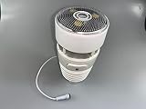
Misol Modbus RTU Ultrasonic Anemometer with Light & UV, Thermo-Hygrometer Sensors WN90LP | $359.99 | Buy on Amazon |
| 3 |

|
Ambient Weather WS-5050 Garden Bundle | $462.67 | Buy on Amazon |
| 4 |

|
BTMETER Hot Wire Anemometer Dual Port Manometer Kit - 12 Selectable Units | $151.99 | Buy on Amazon |
| 5 |
|
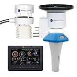
Ambient Weather WS-5000 Pool Bundle | $504.38 | Buy on Amazon |
U = (L/2)(1/t+ − 1/t−)
c = (L/2)(1/t+ + 1/t−)
These inverse-time equations are used in published calibration work and an American Meteorological Society prototype paper. The signs depend on the chosen path direction: define which direction is positive and keep that convention throughout processing.
The times in the equations must represent acoustic transit, not the whole electronics response. Transmitter, receiver, transducer, and switching delays can differ by direction. Measure those delays and subtract them before calculating velocity; otherwise, even a stationary instrument can report a false wind component.
What’s actually slowing this PC down?
Pick the symptom - the matching free tool is one click away.
#1 Best Overall
- Ultrasonic Wind Speed Measurement: Measures wind speed accurately from 0 to 70 meters per second using advanced ultrasonic technology
- Ultrasonic Wind Direction Detection: Captures wind direction across the full 360-degree range with precision ultrasonic sensors
- Wide Atmospheric Temperature Range: Monitors temperature from -40 to 80 degrees Celsius for comprehensive weather data collection
- High Integration Portable Design: Features compact and lightweight construction with quick installation and retraction capabilities for easy transport and deployment
- Reliable Low Power Operation: Delivers high reliability with micro power consumption technology ensuring extended operation in various meteorological conditions
What a complete build needs
Acoustic head
Build a rigid support that holds matched, opposed transducers at a measured path length. The distance and alignment should remain stable as temperature and handling change. Protect the acoustic apertures from rain and contamination without placing material in the sound path. Record the actual geometry, including transducer positions and support dimensions, because those affect both the path calculation and airflow.
Transmit and receive electronics
The electronics must excite one transducer, receive the returning acoustic signal at the other, and support measurements in both directions. A driver, low-noise receive chain, direction switching or multiplexing, and a stable timing reference are the functional building blocks. The exact circuit and transducer frequency depend on the selected transducers and intended operating range; the cited literature does not establish one universal frequency or bill of materials.
Timing and signal processing
Detecting the first signal crossing a threshold is simple, but noise or waveform changes can shift that crossing. Validate detections and reject weak or ambiguous arrivals. Cross-correlation or matched filtering can estimate arrival time from the received waveform; an open-source implementation uses matched filtering and estimates zero-wind delay from path length and sound speed. A build should record signal quality and rejected measurements as well as accepted times, so bad timing is distinguishable from real wind changes.
Rank #2
- Measures wind speed/direction, temp, humidity, air pressure, light/UV, and rain—all in one unit
- Ultrasonic wind sensors + Haptic rain sensor for accurate, maintenance-free operation
- RS485 output with Modbus RTU protocol, includes 10m cable and USB adapter for PC connection
- Ideal for developers integrating weather data into custom software systems
- No built-in display—protocol provided for your own data collection program
Computation, logging, and protection
For each path, correct direction-specific delays, calculate the path component, and combine the components into instrument coordinates. Transform them to earth coordinates only when the instrument orientation is known. Useful logged fields include wind speed and direction, sonic temperature derived from sound speed, quality flags, and timing or signal diagnostics. Use a rigid, low-drift frame: supports and transducer bodies can block or deflect flow and create wind-shadow errors.
How many paths are needed?
One opposed pair measures only the wind component along its acoustic path. A second non-collinear path adds another component, allowing a two-dimensional horizontal vector when the paths are arranged and processed appropriately. A three-dimensional vector requires enough independent path directions to resolve three components; simply adding another pair does not guarantee a good 3D measurement if the geometry is poorly conditioned or obstructed.
For a multi-path head, document each path’s length, orientation, and sign convention. Convert measured path components to the instrument coordinate frame using the actual geometry, rather than assuming nominal angles. Any transformation to north/east/up coordinates also depends on the instrument’s leveling and heading information.
Rank #3
- WHAT YOU GET: Includes 1 x WS-5050 Weather Station and 1 x WH31SM Soil Moisture Sensor
- WS-5050 WEATHER STATION: All the benefits of the WS-5000 weather station without the rain gauge. Wireless ultrasonic sensor array measures wind speed/direction/chill, temperature, humidity, dew point, UV, heat index, and solar radiation. Wi-Fi enabled and full-color display included.
- WH31SM SOIL MOISTURE METER: Measures moisture content in the soil from a range of 0%-100% and transmits the information once per 71 sections to the display or Ambient Weather Network. Add up to 8 sensors to your station.
- VIEW LIVE DATA AND SET ALERTS ON AWN APP: Enhanced Wi-Fi enables your station to transmit its data wirelessly to the Ambient Weather Network (AWN) App or desktop version where you can view your dashboard, historical data, graphs, and charts, set alerts, and connect to Amazon Alexa.
- US-BASED SUPPORT: Reach our US-based support team 5 days a week for your pre or post-sale questions and needs.
Design choices that determine performance
Choose the design for the intended wind range and environment, then validate it. There is no literature-backed universal DIY transducer frequency, path length, frame shape, or accuracy. Compare candidate designs using the factors below rather than relying on a single specification.
- Path geometry: number and orientation of paths, measured path length, and the target wind range.
- Acoustics: transducer frequency and bandwidth, received signal-to-noise ratio, and robustness to contamination or weather.
- Timing: timer resolution, arrival-time method, direction-specific delay and delay mismatch, and their stability with temperature.
- Airflow effects: acceptance angle, blockage from supports and transducer bodies, and any shadow correction.
- System integration: power, sampling rate, data interface, environmental protection, and calibration traceability.
These factors interact. Finer timer resolution alone does not ensure accurate wind if the acoustic path is poorly known, the received waveform is unreliable, or the frame distorts the flow.
Recommended Free Tools
Where measurement error comes from
Transit-time and flow effects
A pulse takes a finite time to cross the path, during which turbulent flow can change. The resulting measurement may not represent an instantaneous point wind. Non-uniform flow along the path also means the instrument measures a path-integrated effect rather than wind at one point. A theory paper on sonic anemometry models finite-transit effects; these matter especially when interpreting rapidly varying turbulence.
Rank #4
- Industrial Hot-Wire Airflow Meter - BT-9000F thermal anemometer features a high-sensitivity hot-wire probe that detects even subtle airflow changes. Measures wind speed (0.2–67 MPH / 0.1–30 m/s) with ±5 % ± 1 digit accuracy, and supports five units (m/s, km/h, ft/min, knots, mph). Tempe range: 32~113 ℉ (°C/℉ switchable). Ideal for HVAC diagnostics, duct inspections and airflow analysis
- Telescopic Probe & Flexible Design - CFM Meter with The extendable probe rod (extends 11~38 inch) with a 68-inch cable easily reaches ducts, vents, and confined spaces. The 360° rotatable and bendable sensor head adapts to any angle, making it perfect for measuring in high, narrow, or hard-to-reach areas such as
- Smart CFM/CMM Measurement - No manual calculation needed—just set the duct’s cross-sectional area, and the airflow value appears instantly. Measures 0–999,900 CFM/CMM/CMS with area units (㎡ / ft²) adjustable between 0.001–9999. Simplifies HVAC airflow balancing, system testing, and ventilation efficiency verification
- Wide Range & High Accuracy - Pro Gas Pressure Gauge could measure ±13.79 kPa / ±2.000Psi (Limit max pressure: 30.00 psi) with ±0.3%FS high accuracy. ±0.25%FS repeatability and 0.001 resolution. 11 gas measurement units optional, including mmHg, inHg, ftH₂O, cmH₂O, KPa, Mbar, Bar, Psi, Kgcm², inH₂O, and Ozin². Over-range indication available
- Data Record & Zero-out - Equipped with two 3.18mm tube connectors, the BT-189B digital manometer accurately measures static (positive/negative) and differential gas pressure in HVAC systems. Press"REC" button to record and review max / min / average air pressure data; Short-press "HOLD” button to freeze measurement data and Long-press 5 seconds to clear out remaining data to ensure measure accuracy
Cross-flow and head geometry
Wind across, rather than along, an acoustic path can alter the effective propagation path. Transducer bodies, arms, and other supports can create velocity deficits or a wind shadow, with the magnitude depending on inflow angle and head design. The open-source design documentation describes cross-flow and blockage effects; ASTM’s performance criteria include shadow correction and thermal stability. Treat the mechanical head as part of the measurement system, not as a neutral holder for the electronics.
Direction-dependent delay and temperature
Unequal delays in the two measurement directions do not cancel in the velocity calculation. Electronic components and transducers can also shift timing as temperature changes. Measure zero-wind delay separately for each direction and path, and check whether those corrections remain stable across the intended environmental range.
Independent reader supportYour contribution helps us test, update, and keep practical guides available for everyone.How to calibrate and validate the instrument
- Measure the head: document actual acoustic path lengths, transducer alignment, and path orientations. Use those measured values in processing rather than relying on design drawings alone.
- Establish zero-wind delay: determine delay for every path and direction, and keep the direction-specific corrections separate. Check the instrument with no imposed flow to identify residual offsets.
- Test controlled flow: compare the instrument over its intended speed range and at several inflow angles. Include angles that expose support and transducer shadowing, not just the easiest alignment.
- Compare with a reference: calculate bias, repeatability, and uncertainty from the comparison. State the test conditions and reference used; a calibration result is specific to the tested setup.
- Fit and verify corrections: where measurements show angle-dependent shadow or support effects, fit correction coefficients or a lookup table. Validate corrections against measurements not used to fit them.
- Recheck environmental stability: repeat selected calibration points after thermal cycling or environmental exposure to assess changes in geometry, delay, and acoustic signal quality.
A 2017 calibration study using a spinning-sensor procedure and wind-tunnel comparison reported about 0.3% calibration uncertainty for that tested procedure. It is not a general accuracy specification for a home-built instrument. DIY accuracy must be established from the particular head, electronics, corrections, and validation conditions.
Free tools Windows power users keep installed
One-click scans. No signup required.
Best Value
- WHAT YOU GET: Includes 1 x WS-5000 Weather Station with Color Display and 1 x WH31PF Pool Float Temperature Sensor
- WS-5000 WEATHER STATION: Wireless ultrasonic sensor array measures wind speed/direction/chill, temperature, humidity, dew point, rainfall, UV, heat index, and solar radiation. Wi-Fi enabled and full-color display included.
- WH31PH FLOATING POOL THERMOMETER: A sealed pool thermometer that is waterproof, wireless, and floats on the water's surface. Features an LCD display with temperatures in °F or °C. Sealed with batteries for no maintenance or corrosion.
- VIEW LIVE DATA AND SET ALERTS ON AWN APP: Manage your sensor on your dashboard and set alerts on the free AWN (Ambient Weather Network) App or desktop version at www. ambientweather.net
- US-BASED SUPPORT: Reach our US-based support team 5 days a week for your pre or post-sale questions and needs.
Using ASTM as a performance checklist
ASTM D6011-96(2022) is a useful framework for evaluating sonic anemometer/thermometers that use inverse-time solutions. ASTM describes its method as providing a standard way to evaluate measurement of wind-velocity components and sound speed. Its listed performance topics include:
- acceptance angle and acoustic path length;
- system delay and delay mismatch;
- thermal stability and shadow correction; and
- velocity calibration range and velocity resolution.
Use these topics to structure a test plan and report what was measured. Citing a standard as a checklist does not mean a DIY instrument has passed it; conformance requires evaluation under the applicable method.
Quick Recap
Product prices and availability are accurate as of the date/time indicated and are subject to change. Any price and availability information displayed on Amazon at the time of purchase will apply.

