
The Tool Desk
Outbyte Driver Updater FREEFix the driver behind crashes, sound loss and screen glitchesFind Drivers →Outbyte PC Repair FREEClear out junk files and repair common Windows errorsFree Scan →A battery pack needs more than a protection board. A properly matched battery management system (BMS) monitors cell and pack voltage, current, and temperature, and disconnects the pack when operation crosses its specified safety limits. Safe design also depends on compatible cells and charging equipment, suitable fusing and current interruption, insulation, thermal management, and mechanical protection. A BMS reduces risk; it cannot make a damaged pack, unsuitable charger, or poor pack design safe.
What does battery-pack protection do?
Battery-pack protection is a set of measures intended to keep cells within their specified operating limits and to limit the consequences of faults. A BMS is the electronic monitoring and control component of that system. GB 44240-2024 defines a BMS as an assembly connected to a battery system with protective functions against overcharge, overcurrent, overheating, overcooling, and overdischarge where applicable.
A properly designed, functioning BMS can disconnect a battery or pack from its external circuit when it operates outside its safe operating region, as the U.S. Consumer Product Safety Commission explains. That function is important, but protection is not a guarantee that every internal fault will be detected or stopped before damage occurs.
Which hazards must a pack be designed to control?
| Hazard | Why it matters | Relevant protection |
|---|---|---|
| Overcharge | Charging beyond a cell’s permitted voltage can cause electrode and electrolyte decomposition, lithium plating, and self-heating. | Voltage and current monitoring should interrupt charging when the cell or pack exceeds manufacturer-specified limits. EU battery safety requirements include tests of protection by voltage control or current control. |
| Over-discharge | Excessive discharge can cause polarity reversal and damage to the copper current collector. Subsequent plating can contribute to an internal short. | Cell-voltage monitoring should stop discharge at the cell manufacturer’s specified lower limit. |
| Overcurrent or external short circuit | Abnormal current can cause rapid heating, arcing, or loss of electrical isolation. | Electronic current protection and appropriately selected fuses or other current-interruption devices address different parts of the fault response. |
| Unsafe temperature | Operation outside the cell’s permitted temperature range can cause damage. Charging at low temperature can promote lithium plating and internal shorts. | Temperature sensing and control should prevent charging or discharging outside the cell and pack limits where required. |
| Thermal runaway and propagation | A failing cell can release heat, gas, and fire. The resulting heat may cause nearby cells to fail in turn. | Electronic cutoffs help control electrical causes, while pack design must also mitigate or test for heat and fire propagation between cells. |
| Mechanical or manufacturing damage | Crushing, drops, vibration, puncture, separator damage, contamination, or electrode misalignment can create internal shorts. | Cell quality controls, robust assembly, enclosure design, and mechanical protection address risks that a BMS may not detect early enough. |
The UK government describes thermal runaway as the central event in lithium-ion battery hazards because it can involve rising temperature or fire, increasing pressure, and release of toxic gases. This is why electrical cutoffs alone are not a complete fire-safety strategy.
#1 Best Overall

- 5PCS 3S BMS 20A Li-ion Lithium Battery 18650 BMS Charger PCB BMS Protection Board For Drill Motor 12.6V Lipo Cell Module
- Charging voltage: 12.6V
- Maximum output current: 20A
- Suitable range: For nominal voltage 3.6V 3.7V lithium battery(Including 18650,26650, lithium polymer batteries)
Is a BMS the same as a battery protection board?
The terms are often used loosely. A protection board commonly refers to a circuit board that monitors selected conditions and switches the battery off when a limit is exceeded. A BMS may include those functions, but can also provide cell balancing, temperature inputs, system status, or communications. The name on a product listing does not establish which functions it actually supports.
Check the manufacturer’s documentation for the board’s supported chemistry and series count, monitored cell voltages, current limits, temperature inputs, balancing behavior, fault response, and any communications features. A board that only provides basic cutoff protection is not equivalent to a complete battery-system safety design.
Rank #2

- 【DALY BMS】Adopt injection molding sealing process, with dustproof, shockproof, waterproof, anti-accumulation function
- 【Multi -Function Protection】Over-charging,Over-discharging,Over-current,Temperature and Short-circuit protection functions.--- ISO/ FCC/ RoHS/ PSE/ CE APPROVED
- 【New Upgrade】Smaller size; Pre-charging function; 100mA Passive balancing current; Low temperature rise;Consistent Chg/Dischg cuurrent.
- 【Easy to install】Easy to plug and unplug, which allows you to effortlessly create an electrical connection between the battery pack and the BMS.
- 【Note】Standard BMS dosen't have communication functions.If you need smart BMS, active balancer, parallel module or other accessories, please contact online customer service.We offer 24-hour one-on-one customer service and lifetime technical support.
What protection is needed beyond the BMS?
- Compatible cells and charger: Use cells intended for the pack configuration and a charger designed for that chemistry and series count. The charger must remain within the cell and pack manufacturer’s charging limits.
- Current interruption: Select fuses or other protective devices for the system’s normal current and fault conditions. A BMS switch and a fuse have different roles; one should not be assumed to replace the other.
- Temperature management: Place and configure sensors in accordance with the cell and pack design. Consider both operation in the allowed temperature range and how heat is managed if a cell fails.
- Insulation and electrical layout: Protect against shorts, arcing, and loss of isolation through appropriate spacing, insulation, wiring, and assembly practices.
- Mechanical protection: Design the enclosure and cell supports for the expected impact, vibration, and environmental conditions, without creating new hazards through trapped heat or pressure.
- Propagation mitigation: Assess how heat, fire, and gases from a failed cell could affect adjacent cells and the surrounding installation. Pack-level tests or design measures may be needed in addition to electronic protection.
How do you choose a battery protection board?
- Identify the exact cells and chemistry. Obtain the cell manufacturer’s voltage, current, and temperature limits. Do not select cutoffs from a generic chart or copy settings from a different cell type.
- Confirm the series count and pack configuration. The board must support the number of cells in series and the intended arrangement. Verify whether it monitors individual series groups as required by the design.
- Match current ratings to the whole system. Compare the board’s documented continuous and peak charge and discharge current ratings with the pack’s intended operating and fault conditions. Confirm how long any peak rating applies and the conditions under which it is specified.
- Check voltage cutoff behavior. Confirm the overvoltage and undervoltage thresholds, tolerances, delay, and recovery behavior against the cell manufacturer’s limits and the pack design. Exact values are chemistry- and cell-specific.
- Review temperature protection. Check how many sensor inputs are supported, where the sensors are intended to be placed, and what the board does for charging and discharging at high or low temperatures.
- Check balancing and short-circuit response. Establish whether balancing is included, what type it uses, and whether the board’s documented short-circuit response is suitable for the pack’s design. Do not infer response capability from a product title alone.
- Verify the charger and system interface. Ensure the charger is intended for the chemistry and series count, and that its operating limits work with the board’s cutoff behavior. If the board offers communications, confirm that the connected equipment supports the same interface and signals.
- Assess installation and compliance needs. Check isolation, enclosure, environmental conditions, and applicable product or installation requirements. Depending on the system and market, relevant standards may include BS EN 62619, UL 1973, UL 9540, or IEC 62933-5-2. A board’s stated compliance does not by itself establish that the finished pack or installation meets every applicable requirement.
If manufacturer specifications or fault-response details are missing, the board cannot be reliably matched to the cells and system. Battery-pack design and assembly should be assessed by someone qualified for the application, particularly where a fault could cause fire, injury, or property damage.
Do Li-ion and LiFePO4 packs use the same settings?
No. Lithium-ion is a broad category, and cell chemistries have different voltage and temperature limits. LiFePO4 is one lithium-based chemistry; its protection thresholds must still be chosen for the specific cell and pack rather than assumed from a generic lithium-ion setting.
Rank #3

- Voltage :dc14.6v Discharge current :100a Charging current (same port):≤50a Internal resistance of main circuit conduction :≤5mq Discharge overcurrent protection :600+ 10a Power consumption :≤40ua Hibernation overdischarge power consumption :≤10ua
- High quality MOS tube with low internal resistance, all aluminum material, fast heat dissipation
- When any series of battery cells or wires in the battery pack fault short circuit can disconnect the output power protection battery pack
- Overcharge protection, balance protection, over discharge protection, over current protection, short circuit protection, electrostatic protection, weak current switch
- [Satisfactory Service]: We Provide 24-hour online service,If you encounter any problems, Please email SELLER SUPPORT (Not Amazon support), we will give you a perfect solution.
| Selection factor | What to verify |
|---|---|
| Chemistry and cell model | Use the specified limits for the exact cells; do not transfer thresholds between chemistries or cell models. |
| Series and parallel arrangement | Confirm the board supports the series count and intended pack configuration. |
| Current capability | Match continuous and peak charge and discharge ratings to the system requirements and the manufacturer’s stated test conditions. |
| Temperature protection | Verify sensor support, relevant operating limits, and cutoff behavior for charging and discharging. |
| Pack construction and use | Consider enclosure, isolation, cooling, mechanical exposure, and the consequences of cell-to-cell propagation. |
Can a BMS prevent a battery fire?
A BMS can help prevent some electrical operating conditions that could damage cells, and disconnecting an unsafe pack can reduce risk. It cannot guarantee that a battery will not catch fire: mechanical damage, manufacturing defects, internal shorts, incompatible charging equipment, or thermal propagation may not be prevented by the board’s electronic controls alone.
There is no single failure-rate or fire-prevention percentage that applies to all battery packs. The relevant evidence depends on the cells, pack design, use conditions, and tests performed; a protection-board rating alone is not a universal measure of pack safety.
Quick Recap
Best Value
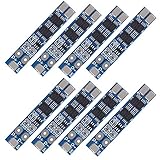
- HIGH-ACCURACY, HIGHLY DURABLE: High-accuracy voltage detection circuit, fine workmanship and durable, Effective life greater than 50000 hours.
- Use for variety of capacities and various shapes 3.7V lithium batteries,Massager battery pack, LED light backup power supply, solar street light battery pack, monitor standby power supply, etc.
- Over-discharge protection, overcurrent protection, overcharge protection, short circuit protection; A combination of 4 safety features that work together to provide ultimate protection for your devices.
- MOS transistor can control the battery charge and discharge, low standby current consumption.
- ATTENTION: Strictly according to the diagram wiring: B+: Battery V+ Positive, B-: Battery V- Negative, P+: Output / Charging V+, P-: Output / Charging V-, MB: The connection point between the batteries.Otherwise it will cause damage to the chip. Do not mix the good battery and poor battery to use. The internal resistance of 3 battery capacity are closer will be better.
Rank #4

- [Product Information]:Working voltage: 1.8V-4.5V,Suitable for ternary lithium, lithium iron phosphate, lithium titanate.Working principle, the capacitor fit transfers the charge mover, the equalization board is connected to the battery, and the equalization is started. The original new ultra-low internal resistance MOS, 2OZ copper thickness PCB,Equilibrium current 0-5.5A, the more balanced the battery, the smaller the current, with manual sleep switch, sleep current mode is less than 0.1mA, the balance voltage accuracy is within 5mv! The quiescent current is about 12 mA. It is recommended that the battery capacity is 60-300AH.
- [Protection switch]: With under-voltage sleep protection, the voltage will stop automatically when the voltage is lower than 3.0V, and the standby power consumption is less than 0.1mA.
- [Satisfactory Service]: We Provide 24-hour online service,If you encounter any problems, Please email SELLER SUPPORT (Not Amazon support), we will give you a perfect solution.
- Before connecting the equalization board, be sure to check whether each battery is wired correctly, and do a good job of insulation. otherwise it will short-circuit and burn the board. If Buyer short-circuits and burns the board, Buyer needs to bear the responsibility instead of returning it. Thank you for acting with conscience.
Product prices and availability are accurate as of the date/time indicated and are subject to change. Any price and availability information displayed on Amazon at the time of purchase will apply.

