
Free tools Windows power users keep installed
One-click scans. No signup required.
You can use a TSOP1738-style infrared receiver with an Arduino to detect commands from a compatible IR remote, then use the decoded command as an input to your project. The receiver handles the incoming IR signal; the Arduino and its sketch interpret it and decide what to do. The TSOP1738 is specified for a 38 kHz carrier, but Mouser lists this exact part as obsolete, so check the part’s lifecycle and compatibility before building around it.
What the TSOP1738 does in an Arduino automation project
The TSOP1738 is a demodulating infrared receiver intended for remote-control signals associated with a 38 kHz carrier. It is an input device for receiving commands—not a general-purpose proximity, motion, or ambient-light sensor. A compatible remote sends an IR signal, the receiver produces an output signal, and an Arduino library can decode that signal into a value your sketch can use.
For example, a decoded button press could tell a project to change a setting or activate a separate control circuit. The receiver itself does not switch a load. Any motor, lamp, or other load needs a suitable driver or relay stage designed for its electrical requirements; do not connect a household or high-current load directly to an Arduino pin.
Parts and compatibility to check
- An Arduino-compatible board. The cited Arduino Project Hub example uses an Uno Rev3.
- A TSOP1738 or another verified 38 kHz IR receiver with a pinout and supply specification suitable for your circuit.
- An IR remote whose carrier and signal can be received and decoded by the receiver and the library you choose. A 38 kHz receiver does not guarantee compatibility with every remote or protocol.
- Suitable wiring and prototyping supplies, such as a breadboard and jumper wires.
- A separate, properly rated driver or relay circuit if the decoded command will control a load.
Mouser identifies the TSOP1738 as a 38 kHz receiver and lists its lifecycle as obsolete. Vishay’s TSOP381/383/385 and TSOP373/375 families include 38 kHz variants, but they are not automatically drop-in replacements. Compare the exact ordering code and datasheet before substituting a part.
The Tool Desk
Outbyte PC Repair FREEClear out junk files and repair common Windows errorsFree Scan →Outbyte Driver Updater FREEFix the driver behind crashes, sound loss and screen glitchesFind Drivers →#1 Best Overall

- 20pcs TSOP1738 Infrared Wire Terminal 38K Sensor
Example wiring
The Arduino Project Hub example connects its depicted receiver as follows. Treat this as that project’s wiring, not a universal pinout for every TSOP1738 package or receiver module.
| Receiver connection in the example | Arduino connection |
|---|---|
| First/left pin: OUT | Digital pin 11 |
| Middle pin: GND | GND |
| Third/right pin: VCC | 5 V |
Before applying power, identify the pins from the datasheet for the exact component or module in hand. The Vishay TSOP381/383/385 documentation, for example, specifies pin 1 as OUT, pin 2 as GND, and pin 3 as VS; do not assume that a different package or board presents the pins in the same physical orientation. Also verify that the receiver’s supply limits support the voltage you plan to use.
Rank #2

- TSOP38238 Supply voltage: 2.5 V to 5.5 V
- TSOP38238 Insensitive to supply voltage ripple and noise
- TSAL6200 Peak wavelength: λp = 940 nm
- TSAL6200 Suitable for high pulse current operation
- TSAL6200 Angle of half intensity: ϕ = ± 17°
How the Arduino sketch processes a remote command
The cited Arduino Project Hub tutorial uses the IRremote library. Its software flow is to start serial communication, enable IR reception, check for a decoded result, print the value in hexadecimal to the Serial Monitor, and resume reception. The tutorial was published in 2022, and library APIs can change, so use the examples and API documentation for the version installed in your Arduino IDE rather than assuming older code will compile unchanged.
- Install or select an IR decoding library that supports your receiver and remote’s signal format.
- Configure the receiver input and initialize serial output if you want to inspect decoded commands.
- Start reception using the API for the installed library version.
- When a decoded result is available, inspect its value and map the command you need to an action in your sketch.
- Resume reception as required by the library so the Arduino can receive the next command.
For initial setup, printing received values is useful: press remote buttons one at a time and note which decoded value corresponds to each button. Then use those values in your project logic. Do not assume a hexadecimal code from one remote will match another remote or library configuration.
Recommended Free Tools
Rank #3

- 10pcs TSOP1738 infrared wire terminal 38k sensor
Choosing a replacement for an obsolete TSOP1738
Search for a “38 kHz IR receiver module” or compare manufacturer receiver components when the exact TSOP1738 is unavailable. A matching carrier frequency is only one part of compatibility. Compare the actual part’s documentation and seller’s lifecycle or stock information before purchase.
- Carrier frequency and remote compatibility: Confirm that the receiver is appropriate for the remote’s carrier and signal pattern.
- Protocol and AGC behavior: Receiver families can differ in how they handle burst patterns and noise, which can affect reception.
- Package and pinout: Check physical orientation, lead arrangement, and mounting requirements.
- Electrical specifications: Verify supply voltage and current limits, output characteristics, and operating conditions.
- Availability: Confirm lifecycle and stock with the seller; a manufacturer family page is not proof that a specific ordering code is in stock.
Vishay’s TSOP381/383/385 and TSOP373/375 datasheets provide current family documentation and 38 kHz variants, but their distinct family characteristics mean you should verify the specific device rather than treat either family as a guaranteed direct substitute.
Quick Recap
Best Value

- 10PCS IR Receiver 38 kHz Remote Infrared Module TSOP4838 DIP-3
Rank #4
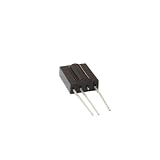
- 5pieces TSOP1738 DIP-3 Sensor Modules
- 5pieces
Troubleshooting missed or incorrect commands
- No output or no decoded results: Recheck the receiver’s pinout and orientation against its own datasheet, then confirm the Arduino input connection and supply voltage.
- Reception works inconsistently: Make sure the remote is aimed toward the receiver and test without obstacles. The available sources do not establish a universal operating range.
- Some remotes work but others do not: Check carrier and protocol compatibility. A 38 kHz rating alone does not establish support for every remote.
- The sketch does not compile: Check the installed IRremote version and adapt the sketch to that version’s API and examples; the cited project’s code dates to 2022.
- Supply-related glitches: Vishay notes in its application circuit that “R1 and C1 [are] recommended in case there are strong ripple or spikes on the supply line.” This is conditional manufacturer guidance, not a mandatory addition to every breadboard circuit.
Product prices and availability are accurate as of the date/time indicated and are subject to change. Any price and availability information displayed on Amazon at the time of purchase will apply.

