
Outdated Drivers Are Slowing You Down
One free scan finds every outdated or missing driver and matches the right update for your exact hardware.Free scan · exact hardware matchWindows Errors? Fix Them Before They Spread
Repair common Windows errors and clear accumulated junk for a smoother, more stable PC - no reinstall needed.Free scan · no reinstallOIF’s Common Electrical I/O (CEI) project is a family of interoperability agreements for high-speed electrical links between chips, packages, circuit boards and optical modules. It sets electrical and jitter requirements so links designed by different vendors can work together; it does not define a complete communications protocol or a product’s pinout, management interface or power supply.
Why OIF created CEI
OIF proposed the Common Electrical I/O project in document 2002.571.01, and approved it at its Orlando plenary on November 14, 2002. The original problem was how to support faster electrical interfaces for payloads of 10 Gbps and above while enabling greater density and/or lower cost. The proposal named SFI, SPI and TFI among the interfaces in view.
As systems moved to higher signaling rates, engineers needed more than a nominal speed to design a link. The transmitter, receiver and intervening channel all affect whether signals arrive in a form the receiving equipment can interpret. CEI provides shared requirements for those electrical and jitter behaviors, creating an interoperability layer that can be used across applications.
What CEI specifies—and what it leaves to other standards
CEI is developed by OIF’s Physical and Link Layer Working Group as a set of implementation agreements for interoperability at electrical and optical interfaces. A CEI link is point-to-point, uses balanced differential pairs with nominal 100-ohm differential impedance, and signals in one direction. The transmitter, receiver and channel requirements, along with jitter limits and compliance methods, depend on the applicable CEI clause.
#1 Best Overall

- 【For Industrial Cameras】This hirose 6 pin female cable is suitable for Basler racer GigE and runner, Keyence, Cognex, for Sony CCD, Hikvision, Baumer, Allied Vision, Imaging Source, GigE, JAI, Daheng, AVT and more industrial Machine Vision cameras with Hirose 6 pin Male Connector to achieve power supply I/O trigger and data transmission.
- 【High Flex Drag Chain】High Flexible cable, resistant to high temperature and corrosion, designed for demanding drag chain environments. Double shielded braid + foil design for maximum protection from EMI/RFI.
- 【Widely Compatible】Provides a reliable connection for CCD cameras in machine vision and robotics, Industrial Imaging, ensuring high-quality image capture for precision automation and control.
- Plug A: HR-10A-7P-6S Hirose 6 Pin Female; Plug B: Open End for DIY. Cable Length: 3m/9.84ft. We can customize cables with other length, please send a message to us before making the order.
- Every cable was tested to ensure that there are no short circuit, no potential breakdown problems before shipping. Please let us know if the cable you received is defective or doesn’t work. We will solve the problems properly or send you a new replacement at once.
CEI is not the whole link or system specification. A separate protocol supplies synchronization or framing functions, and other specifications or design documents must cover system functions CEI leaves outside its scope.
- Not specified by CEI: connector pinout, management interface and power-supply requirements.
- Also outside CEI: higher-level functions such as addressing and error control.
- Still essential to a working product: the protocol and system-level requirements that sit above the electrical interoperability agreement.
This boundary matters when comparing products: compliance with an electrical agreement does not, by itself, establish that two systems share a connector assignment, management behavior or higher-level protocol.
How the CEI document is organized
CEI is clause-based rather than a single specification that repeats every requirement for every application. The CEI-05.3 agreement describes a master document extended by follow-on clauses for new functions, corrections and additions; unchanged clauses are not repeated. That structure lets application specifications evolve on separate schedules while using common electrical requirements where applicable.
Rank #2

- Connector Shape: HDMI 19 Pin Male to HDMI 19 Pin Male
- Cable Length: Approx. 5.9 ft (1.8 m) (not including connector)
The latest agreement identified here is OIF-CEI-05.3, approved July 17, 2025. It covers electrical and jitter interoperability agreements for 6G+, 11G+, 25G+, 56G+ and 112G+ I/O. OIF’s front matter describes the organization as having more than 160 member companies in 2025.
How to compare CEI generations and reach classes
A label such as 112G identifies a family or nominal interface class; it is not enough on its own to determine the exact bit rate, baud rate, modulation, channel reach or number of lanes in a system. Read the particular clause for those details. Baud rate counts signal symbols per second, while bit rate counts bits per second; they are not interchangeable, especially when modulation carries more than one bit per symbol. Lane count is a separate system-level quantity.
Use the following comparison axes when selecting or interpreting an agreement:
Rank #3

- 【M8 Connector Cable】M8 single ended connector cable,4 pin with gold plating,A coding ,IP67 waterproof led connector,Shielded,24AWG 6.6ft, field wired..Support customization (wire length, connector type, other parameters)
- 【High Quality 】M8 4-Pin Male Circular Aviation Connector use professional high quality black rubber bakeute makes it Insulation and flame retardant.Thread locking mechanism,anti vibration locking design,8mm thread joint.Waterproof Industrial Sensor connector use All-copper-plated metal screw sleeve,pure copper gold-plated contacts,robust and corrosion-resistant,durable,while ensuring the stability and reliability of data and signals.
- 【Safe and Reliable】M8 Waterproof Aviation Sensor Cable 6.6Ft 24 AWG aviation connector cable is made of high quality PVC+PUR Jacket,,which protects the wire against abrasion, resistant to sunlight and chemicals.The rated operating temperature up to 80℃/176℉.24 gauge AWG*4 Conductor,17 strands of 0.16mm 99.99% Oxygen Free Copper Conductors are inside each cable.High Precision Oxygen Free Copper - Compared with aluminum material, it has lower resistance and higher conductivity.
- 【DIY & Quick Installation】M8 Aviation Socket Electrical Cable—No tools required for installation and removal,8mm Field Assembly 4 Pin Connector Cable provide quick and easy connection between field devices and terminal connections, flexible and convenient plug-and-play.Single ended Cable makes you to choose the type of connector at the other end according to your needs -A wider DIY range allow you to freely combine and match to complete the work efficiently and quickly.
- 【Application】The M8 Industrial Circular Connector Cable is suitable for Data Communication and I/O connection on-site installation,and widely used in industrial automation, PLC systems, commercial electronics, such as building construction, high-speed rail, intelligent manufacturing, and the automotive industry.,can be easily connected to proximity switches,photoelectric barriers, flow monitoring devices,sensor devices and ctuator devices and field bus components.
- Rate family: CEI includes legacy 6G, 11G and 25/28G families, as well as 56G and 112G+ families in CEI-05.3. Confirm the clause’s specified signaling rate rather than treating the family name as a full rate specification.
- Modulation: clauses specify the signaling method, including NRZ or PAM4 where applicable. Do not assume a modulation scheme from the family label alone.
- Reach and topology: check whether the target is package, die-to-die, PCB, backplane or module use, and account for connector count as well as trace length.
- Channel and compliance: compare the transmitter, receiver and channel limits together with the stated jitter and measurement methodology.
- System boundary: confirm that separate specifications cover pinout, management, power and higher-level protocol requirements.
The reach labels—very-short (VSR), short (SR), medium (MR), long (LR) and extra-short (XSR)—are useful shorthand for different channel environments. They are not substitutes for the actual clause limits: two links in the same broad class can still have different media, connector arrangements or compliance conditions.
| Agreement or example | What the cited material establishes | How to interpret it |
|---|---|---|
| CEI-6G-SR, in CEI-04.0 | 4.976–6.375 Gsym/s over up to 200 mm of PCB and one connector. | A legacy short-reach example. The range is a symbol rate, not a stated bit rate. |
| CEI-112G-VSR-PAM4, in CEI-05.3 | At least 200 mm of host PCB trace, one connector and 20 mm of module PCB trace. | A PAM4 very-short-reach example with a specified host-to-module channel arrangement. |
| CEI-112G-MR-PAM4, in CEI-05.3 | Up to 500 mm. | A medium-reach example; the distance alone does not replace the clause’s channel and compliance requirements. |
| CEI-112G-LR-PAM4, in CEI-05.3 | Up to 1,000 mm with up to two connectors. | A long-reach example with an explicit connector allowance. |
These figures describe specific examples, not universal maximum distances for every interface carrying a similar generation label. For a design, use the full applicable clause and its measurement conditions; a trace-length figure by itself does not establish that a channel will pass compliance.
What’s actually slowing this PC down?
Pick the symptom - the matching free tool is one click away.
How CEI evolved from earlier interfaces to 112G
CEI-04.0 shows the project’s continuity with earlier OIF electrical interfaces. It includes SxI-5, SFI-4.2, SFI-5.1, SPI-5.1 and TFI-5 alongside CEI-6G, CEI-11G and CEI-25/28G reach classes. CEI-05.3 extends the family’s coverage to higher-rate I/O, including 56G+ and 112G+ agreements.
Rank #4
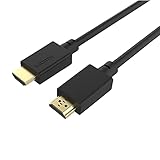
- HDMI CABLES: For multiple device compatibility and entertainment, the TALK WORKS 6ft. HDMI cable offers high speed connection and HD quality that can be used for a variety of events such as game nights, streaming, movie nights, and more.
- WIDE COMPATIBILITY: Our cable supports electronic ARC audio and visual support. This cable supports Ethernet connection with an 8K resolution and 60Hz frequency so you can enjoy improved quality on your flat screen TV.
- HDMI HIGH RESOLUTION: The 8K UHD high speed cable supports up to 7680 x 4320 resolution UHD+ and supports a high refresh rate and low latency televisions for smooth and responsive gaming.
- DURABLE DESIGN: This HDMI to HDMI 6 foot cable has an anti-wear design to last longer and maintain durability and features a gold-plated I/O.
- ABOUT US: TALK WORKS offers tech accessories that make our lives easier and more enjoyable. Our products include phone charging accessories, gaming accessories, charging cables, power banks, and much more.
Generation labels alone do not make two clauses directly comparable. A sound comparison checks modulation, actual symbol or bit rate, reach, channel construction, connector count, jitter requirements and compliance method. It also accounts for whether the clauses target the same position in a system—for example, a package link versus a host-board-to-module channel.
Independent reader supportYour contribution helps us test, update, and keep practical guides available for everyone.Why 112G, 224G and 448G demonstrations matter
OIF’s OFC 2024 release highlighted multi-vendor demonstrations involving 112G and 224G CEI. Such demonstrations are relevant because the project’s goal is interoperability: showing implementations from different vendors operating together can provide evidence that common electrical requirements are useful beyond a single vendor’s design.
An OFC 2026 exhibitor report describes CEI-224G and CEI-448G demonstrations and presents 448 Gbps-per-lane electrical interfaces as a future data-center challenge. Higher per-lane capacity can help systems move more data without scaling lane count at the same rate, but it also raises demands on the electrical channel and on transmitter, receiver and jitter performance. The reach and channel environment therefore matter as much as the headline generation.
Free tools Windows power users keep installed
One-click scans. No signup required.
Best Value

- SlimSAS SFF-8654 to SFF-8654 cable, 8i configurations, supports data rates up to 24Gbps, 100 Ohm impedance, 32AWG, (11#) straight types cable plug.
- Designed for unshielded, internal I/O connectors. High density 74pin offers superior signal integrity performance.
- Compliant with T10/ Serial Attached SCSI (SAS-4) standard, extended to support SAS 4.0. Applicable for servers/ PC, data storage, workstation, data center, devices.
- Ribbon cable interface and assembly options provide low profiles and design flexibility.
- Applicable for servers/ PC, data storage, workstation, data center and etc.
Keep the units and scope clear when reading announcements. The 448 Gbps-per-lane figure is how the cited 2026 report characterizes the interface challenge; it should not be read as a baud rate, a demonstrated universal operating rate, or a statement that every CEI-448G clause has the same reach. Demonstrations indicate industry activity, not a complete system specification or product certification.
What CEI means when designing or evaluating a link
CEI is most useful as a common electrical contract between the endpoints and the channel. To apply it to a real design, identify the exact interface clause, then verify that the intended topology and channel fall within its conditions. The system still needs the specifications that CEI intentionally leaves out.
- Identify the endpoints and use case. Establish whether the electrical path is chip-to-chip, package, board, backplane or host-to-module.
- Select the exact clause. Match the reach class, signaling method and generation to the intended application rather than relying on a broad label such as 112G.
- Model the full channel. Account for trace segments, package or module substrate contributions and connector count as the clause requires.
- Check both ends and the channel. Review transmitter and receiver requirements, jitter limits and the applicable measurement and compliance procedures.
- Complete the system specification elsewhere. Define pinout, management, power, synchronization or framing, and higher-level protocol behavior through the relevant system and protocol specifications.
For procurement or interoperability claims, ask which CEI revision and clause were used, what channel configuration was tested, and which compliance methodology applies. A broad claim of supporting a CEI generation is less informative than a clause-specific statement tied to a defined channel and test conditions.
Quick Recap
Product prices and availability are accurate as of the date/time indicated and are subject to change. Any price and availability information displayed on Amazon at the time of purchase will apply.
Do these 3 things before closing this tab:
1Repair Windows errors before they cause bigger problems2Fix the driver behind crashes, sound loss and screen glitches3Clear out junk files and repair common Windows errors
