
The official manual for a Keysight 3024A is the InfiniiVision 3000 X-Series User’s Guide (publication 9018-03427). It covers both the four-channel analog DSOX3024A and the mixed-signal MSOX3024A, which adds 16 digital channels. Check the model label before following setup or troubleshooting steps.
Download the right Keysight 3024A manual
Keysight publishes a family guide, not a separate operating manual for each 3024A variant. Use the document that matches the task:
- Operating the scope: InfiniiVision 3000 X-Series User’s Guide, publication 9018-03427. It covers front-panel operation, probes, triggering, acquisition, measurements, saving, calibration, and troubleshooting.
- Remote control and automation: InfiniiVision 3000 X-Series Programmer’s Guide, publication 9018-06894. It documents SCPI commands, waveform transfers, status and error handling, and instrument subsystems.
- Specifications and options: Keysight’s 3000 X-Series data sheet.
- Firmware and model support: the MSOX3024A support page. Verify that a download applies to your exact model and region.
For memory sanitization when transferring or disposing of an instrument, look for the applicable declassification and security documentation through Keysight support; do not assume an ordinary user guide covers sanitization procedures.
Identify your 3024A variant
Read the complete model number on the instrument’s front-panel or rear label. “3024A” alone does not establish whether digital logic inputs are present.
Quick wins for a faster PC:
Clear out junk files and repair common Windows errorsFree Scan →Fix the driver behind crashes, sound loss and screen glitchesFind Drivers →#1 Best Overall

- Product is intended for professional use only
- Has four N2140A 200 MHz 10:1/1:1 switchable passive probes
- See more signal detail with 50,000 wfms/sec update rate
- Mask, math, FFT, analog bus, protocol triggering/decode
- Built-in help and training signals
| Feature | DSOX3024A | MSOX3024A |
|---|---|---|
| Analog channels | 4 | 4 |
| Digital channels | None | 16 |
| Bandwidth | 200 MHz | 200 MHz |
| Series | InfiniiVision 3000 X-Series | InfiniiVision 3000 X-Series |
| Operating manual | The same 3000 X-Series User’s Guide | |
| Additional equipment | Analog probes | Analog probes plus compatible digital logic pod/accessories |
Keysight’s DSOX3024A product page identifies the analog-only model; its MSOX3024A support page identifies the mixed-signal version. Do not confuse either 3024A with the 3034A, 3054A, or 3104A, whose bandwidth differs, or with the later 3000T X-Series.
Key specifications and what they mean
The figures below are Keysight-published specifications for the 3000 X-Series 200 MHz class. Operating conditions, active-channel count, options, probes, and firmware affect what is available in a particular setup.
| Specification | Published figure or qualification |
|---|---|
| Analog bandwidth | 200 MHz for both 3024A variants |
| Calculated 10–90% rise time | ≤1.75 ns for the 200 MHz class |
| Maximum analog sample rate | 4 GSa/s with half-channel interleaving; 2 GSa/s with all analog channels active |
| Standard maximum analog record length | 2 Mpts with half-channel interleaving; 1 Mpts with all channels active |
| Optional memory upgrade | Up to 4 Mpts half-channel interleaved and 2 Mpts with all channels active |
| Display | 8.5-inch WVGA |
| Waveform update rate | Keysight states more than 1 million waveforms per second; actual rates depend on acquisition and display conditions |
| Vertical resolution | 8 bits; measurement resolution can reach 12 bits with averaging or high-resolution acquisition |
| Analog input impedance | Selectable 1 MΩ ±1% or 50 Ω ±1.5% |
| Analog input sensitivity | 1 mV/div to 5 V/div for 100–500 MHz models |
| Time base | 2 ns/div to 50 s/div for the 200 MHz model |
| MSO digital acquisition | Up to 1 GSa/s; minimum detectable pulse width 5 ns |
These specifications come from Keysight’s 3000 X-Series data sheet. In particular, maximum sample rate and record length are not necessarily simultaneous all-channel capabilities. For a meaningful capture, note active channels, sample rate, record length, time span, acquisition mode, and whether interleaving or the memory upgrade is in use.
Bandwidth, probes, and measurement limits
A 200 MHz scope does not guarantee accurate measurement of every signal containing energy at 200 MHz. Probe bandwidth and loading, grounding, termination, rise time, and aliasing all affect results. Keysight’s stated 1.75 ns rise time is a specification for the scope class, not a universal rule for deciding whether a particular edge can be measured accurately.
Rank #2

- Product is intended for professional use only
- 2 analog plus 16 digital channels
- Easily view your signals on the 8.5-inch WVGA display
- Capture more data with up to 4 Mpts memory
- See more signal detail with 1,000,000 wfms/s update rate
The data sheet lists a maximum analog input of 135 Vrms or 190 Vpk under its stated conditions. That voltage figure is not permission to probe arbitrary mains or high-energy circuits: Keysight states that the instrument is not rated for CAT II, III, or IV measurement categories and warns about transient overvoltage. Check the scope and probe ratings and measurement-category limits separately before connecting.
Set up a safe first measurement
- Confirm the model and supply requirements. Check the instrument label and local mains requirements before powering it.
- Inspect the equipment. Do not use damaged probes, exposed ground leads, cracked insulation, or damaged connectors.
- Establish protective earth. Connect the oscilloscope to a properly grounded supply before attaching a probe.
- Choose a suitable probe. Confirm its voltage and measurement-category rating for the circuit. Set the channel’s probe attenuation to match the probe.
- Connect the ground safely. Attach the probe ground only to the circuit’s intended measurement reference. Never clip it to a point that may be at a different hazardous potential.
- Start conservatively. Choose a suitable coupling, volts/div, and seconds/div before probing. Check circuit voltage and scope limits rather than relying on AutoScale to make an unsafe connection safe.
- Compensate a passive probe if needed. Follow the manual’s procedure using the scope’s calibration output, then check that the square wave is not over- or under-compensated.
- Check the trace before trusting a reading. Confirm that the waveform is plausible and not clipped, badly triggered, or affected by probe loading before using automatic measurements.
A 50 Ω input can load a circuit substantially; use it only when appropriate for the source and measurement. Check source impedance, probe type, coupling, and input limits first. High-impedance circuits often require a different arrangement.
Display a waveform and take a basic measurement
- Select the input channel connected to the signal and confirm the channel is enabled.
- Set the probe ratio in the channel settings to match the physical probe, then choose AC or DC coupling for the measurement.
- Adjust vertical scale and offset until the full signal is visible without clipping.
- Set seconds/div and horizontal position to show the event or number of cycles you need.
- Configure the trigger. For a periodic signal, choose edge triggering, the signal channel, the relevant slope, and a level near the waveform’s midpoint.
- Choose acquisition behavior. Use Run for ongoing signals, Stop to freeze an acquisition, or Single to wait for and capture a one-time event.
- Add a measurement only after the trace is stable. Select the quantity you need—such as frequency, period, Vpp, RMS, rise time, duty cycle, or delay—and state its definition when recording the result.
AutoScale can help find an initial display for a signal that is already connected safely, but it is not a substitute for checking grounding, probe attenuation, voltage limits, or termination. Cursors are useful when you need to inspect a particular cycle, crossing, delay, or manually selected interval. Automatic measurements are faster on clear repetitive waveforms; noise, clipping, undersampling, bad triggering, or incorrect termination can make either kind of reading misleading.
Choose acquisition and trigger modes for the event
Acquisition modes
- Normal: a general-purpose starting point for ordinary acquisitions.
- Peak Detect: helps preserve narrow excursions that might not appear in a decimated display. Keysight specifies capture of glitches as narrow as 250 ps under stated conditions; this is not a guarantee for every setup.
- Averaging: reduces random noise on repetitive signals. It can also suppress nonrepetitive events, so avoid it when searching for rare glitches.
- High Resolution: can reduce noise and increase effective vertical resolution at appropriate time-base and sample-rate settings.
- Segmented memory: stores separate acquisitions for bursts separated by long idle periods. Keysight lists support for up to 1,000 segments.
- Roll and XY: specialized display modes with different time-base and trigger behavior; consult the guide before treating them like ordinary triggered time-domain acquisitions.
Keysight lists averaging selections up to 65,536 averages. These peak-detect, averaging, and segmented-memory limits are data-sheet capabilities, not assurances that every signal, channel combination, or setting will achieve the same result.
Rank #3
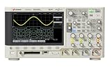
- Product is intended for professional use only
- Easily view your signals on the 8.5-inch WVGA display
- Capture more data with up to 1 Mpts memory
- See more signal detail with 50,000 wfms/s update rate
- Expand your measurement capabilities with an upgrade
Trigger types and controls
- Edge: the usual choice for a signal crossing a selected level in a rising or falling direction.
- Pulse width: finds pulses that are too long, too short, or within a selected range. For the 200 MHz class, Keysight lists a minimum pulse-width duration of 6 ns.
- Runt: finds pulses that cross one threshold but fail to cross another.
- Setup and hold: detects digital timing violations relative to a clock.
- Rise/fall time: finds edges outside a selected transition-time range; the data sheet lists a 3 ns minimum setting for the 200 MHz class.
- Sequence or edge-then-edge: isolates an event that follows another edge after a delay.
Trigger sources can include an analog channel, a digital channel on an MSOX setup, and other listed sources such as external, line, or WaveGen where supported. Auto, Normal, Single, and Force have different behavior: Auto can display without a qualifying trigger, Normal waits for one, Single arms for one capture, and Force requests an immediate trigger. Holdoff can help separate complex repetitive events so the scope triggers on the intended part of the pattern.
Save data so another person can reproduce the result
Use the scope’s save functions appropriate to what must be preserved: a setup for repeatable instrument configuration, a screenshot for visual documentation, or waveform data for numerical analysis. Prefer the native waveform format when the capture needs to be restored on the instrument. If exporting CSV or another readable format, verify the scaling, units, time origin, sample interval, and channel identity rather than assuming the file carries all context.
Record the measurement conditions alongside exported data:
- Probe type and attenuation, coupling, and input termination.
- Bandwidth limit, active channels, acquisition mode, sample rate, record length, and time span.
- Trigger source, slope, level, and mode.
- Firmware version and any relevant installed options.
Exact menu labels and file-format behavior can depend on firmware and configuration; use the manual for the installed revision rather than assuming a menu path from another model family.
Recommended Free Tools
Rank #4
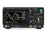
- Product is intended for professional use only
- 50 MHz bandwidth
- 1 GSa/s sample rate
- 200k points
- Built-in 20 MHz function generator
Firmware, support, and remote control
Keysight’s Hong Kong MSOX3024A support page displayed firmware version 2.67, released August 31, 2025, when checked for this article on October 8, 2026. Firmware listings can change and may vary by product page or region, so consult the support page for the exact model before updating.
- Record the installed firmware version and preserve important setups and waveform files.
- Confirm that the download is intended for the precise model family; do not assume firmware or options transfer from a 3000T or another Keysight series.
- Read the release notes, and do not interrupt instrument power during an update.
- Do not assume an update adds licensed hardware features.
For SCPI automation, use the separate 3000 X-Series Programmer’s Guide, not command examples for the 3000T, 4000, or Infiniium families. It organizes commands by common IEEE 488.2 commands and instrument subsystems, including acquisition, display, measurements, waveform data, system status, and error handling. Confirm command syntax and waveform interpretation in the guide edition that applies to your scope before building an automated workflow.
Troubleshoot common 3024A problems
| Symptom | Likely checks and recovery |
|---|---|
| No waveform | Confirm the correct channel is enabled, the probe ratio matches, coupling is suitable, and the time base is in range. Inspect probe connections and grounding before using AutoScale. |
| Trace rolls or changes constantly | Check trigger source, slope, and level. Select the signal channel and place the level near the waveform midpoint; use an appropriate trigger mode. |
| Trigger is stable but shows the wrong event | Try Single for a one-time event, adjust holdoff for repetitive patterns, or use a more specific trigger type. |
| Narrow glitch is missing | Try Peak Detect, a shorter time/div setting, or segmented acquisition for separated bursts. Verify sampling and trigger setup. |
| Signal appears clipped | Increase volts/div or adjust offset; check whether 50 Ω termination is loading the source and whether the probe setting is correct. |
| Measurements fluctuate | Stabilize triggering and inspect noise, clipping, sampling, and probe compensation. Averaging can help with repetitive signals but may hide nonrepetitive events. |
| MSOX digital channels look wrong | Check the logic pod connection, ground reference, and threshold settings against the signal’s logic levels. |
| Remote communication fails | Confirm the interface and instrument address, then check the 3000 X-Series Programmer’s Guide for connection setup, status, and error-query procedures. Do not substitute commands from another Keysight family. |
These checks are starting points, not guaranteed fixes. The User’s Guide provides model-family operating and troubleshooting detail; consult it when a symptom persists or the instrument reports an error.
What to check before buying a used 3024A
A used unit’s condition and configuration can matter as much as its model designation. Inspect the instrument in person where possible, and verify service history and options before relying on it for calibrated work.
- Confirm whether the label says DSOX3024A or MSOX3024A and whether the digital pod/accessories are included if needed.
- Check display condition, buttons, knobs, fan noise, input connectors, and probe insulation.
- Ask for calibration status and service history; factor the cost of calibration or repair into the purchase decision.
- Verify installed memory options and any licensed features rather than assuming the advertised configuration.
- Confirm the included probes are appropriate and correctly rated for the intended measurements.
The analog-only DSOX3024A suits four-channel analog work; the MSOX3024A is the variant to consider when correlating analog signals with up to 16 digital logic channels. A newer platform may be a better fit if warranty, current procurement availability, deeper memory, or newer connectivity is more important than the cost of a used 3000 X-Series instrument. Keysight’s DSOX3024A product page presents procurement options that may depend on region and account; it does not establish universal current availability or price.
Quick Recap
Product prices and availability are accurate as of the date/time indicated and are subject to change. Any price and availability information displayed on Amazon at the time of purchase will apply.

