
Do these 3 things before closing this tab:
1Clear out junk files and repair common Windows errors2Scan for outdated or missing drivers - takes under a minute3Repair Windows errors before they cause bigger problemsChoose an X-capacitor discharge function by starting with the capacitor’s maximum value and the required residual voltage and discharge time, then check the controller’s exact variant, input-sensing method, topology, and standby-power budget. “Capacitor discharge IC” is not a universal class of interchangeable stand-alone parts: the function is commonly integrated into a switching controller or implemented elsewhere in the supply.
Define the capacitor, safety target, and standby budget
An X-rated capacitor is connected across the AC input as part of the EMI filter. After the supply is unplugged, it can retain a hazardous voltage at the plug, so the design needs a discharge method appropriate to the product and the markets where it will be sold.

First establish the largest X-capacitance in the design, including tolerance and any configuration that changes the total capacitance. Then identify the residual-voltage and time requirement that applies to the product. Texas Instruments’ UCC25640x datasheet, Rev. F, revised August 2026, summarizes IEC 60950 and IEC 60065 as requiring a discharge time constant below 1 second. It summarizes IEC 62368 as requiring the X-capacitor voltage to be below 60 V two seconds after AC unplug when capacitance is 300 nF or more. This is TI’s summary of those standards, not a substitute for checking the currently applicable edition, product scope, and compliance requirements.
Finally, set the standby-loss budget. A passive resistor continuously dissipates power while AC is connected; an active design can avoid that continuous bleed loss, but adds disconnect detection and a switched discharge path that must operate reliably.
Recommended Free Tools
#1 Best Overall
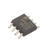
- Part Number:CAP002DG SOP8
Choose between passive and active discharge
Passive bleeder resistor
A resistor, or resistor network, connected across the X-capacitor provides a simple continuous discharge path. Its trade-off is standing loss whenever the supply is connected to AC. TI’s UCC25640x datasheet gives a manufacturer example for a typical 60 W to 100 W supply with 330 nF capacitance: 3 MΩ total bleed resistance dissipates 17.63 mW at nominal high line of 230 V. That is an example, not a universal resistor-sizing recommendation.
The same datasheet states, in its design context, “For every 100nF of capacitance, add a maximum bleed resistor of 10MΩ in parallel.” Do not apply that statement as a stand-alone design rule: calculate against the actual discharge target, circuit conditions, component ratings, and applicable compliance requirements.
Rank #2

- (PRICE/TC) AUTOMATIC X CAP DISCHARGE IC
- 105DEG C
- IC FUNCTION:ZERO LOSS AUTOMATIC X CAPACITOR DISCHARGE IC
- IC PACKAGE TYPE:SOIC
- NO. OF PINS:8PINS
Active switched discharge
An active scheme detects AC disconnect and then switches on a path to discharge the capacitor. It can reduce the continuous loss of a passive bleeder, but selection must account for how the controller senses line presence, detection latency, and behavior during brownouts or transients.
For example, the UCC25640x implementation monitors AC zero crossings through its HV pin. Its datasheet describes a staircase test current; at the highest test-current setting, four missed zero crossings confirm AC disconnect, after which discharge current is enabled for 350 ms. These are specific device behaviors, not general characteristics of active-discharge controllers.
Rank #3

- High Voltage 1000V Capacitor Discharge Pen:This capacitor discharge tool enables the safe and fast discharging of capacitors with a 2V-1000V range, safely handling all capacitors at 1000V and below. Preventing electric shocks and protecting sensitive equipment. A must-have discharge tool for electronic maintenance and repairs.
- Compact & Ergonomic for Easy One-Handed Use:The Capacitor Discharge Tool design is portable and easy to handle, ensuring comfort and convenience for one-handed operation. Ideal for various spacings and use in tight spaces.The capacitor discharge pen enables safe and fast discharging of all high-voltage capacitors in automotive LED lights, HVAC systems, household appliances , digital camera , camcorder , TV, car, consoles and other equipment.
- LED Indicator for Easy Monitoring:Our Capacitor Discharge tool built-in LED light indicates when discharging occurs, ensuring safe and accurate usage. Note: This discharge tool is not designed for battery discharging.
- Polarity-Free, Spark-Free, Safe:The intelligent discharge pen operates safely with no polarity, Suitable for AC/DC capacitor discharge. This capacitor discharge pen provides maximum safety protection and reduces the risk of accidents during capacitor discharge & maintenance.
- Capacitor Discharge tool for Home Maintenances:Quickly discharges residual energy from capacitors to protect operators and products. Essential capacitor discharge tool for electrical maintenance and repair and power capacitor DIY enthusiasts.
TI’s PMP10804 offline flyback reference design uses UCC28630 active discharge circuitry to reduce standby power and eliminate the standing loss of conventional discharge resistors. TI describes that reference design as a 100–138 V AC input, isolated 24 V/4 A output (96 W) supply, and reports over 86% average efficiency and less than 100 mW no-load consumption. Those are figures stated for that reference design, not guaranteed results for another implementation. See TI’s PMP10804 reference design.
Compare documented controller candidates
The following TI devices are documented starting points, not a complete market survey and not interchangeable parts. Feature support and quantitative limits must be verified in the datasheet for the exact device and orderable part.
| Candidate | Documented fit | Checks before selection |
|---|---|---|
| UCC256402 / UCC256404 | LLC controller family; active X-capacitor discharge is available in feature-enabled variants. TI’s UCC25640x datasheet states support for up to 5 µF in variants that include the discharge function. | Confirm discharge support for the exact variant, package, voltage-sensing method, input range, auxiliary supply and startup needs, and compatibility with the full LLC/PFC design. UCC256403 lacks high-voltage startup and requires an external auxiliary supply; some family variants disable X-capacitor discharge. Check the UCC25640x datasheet. |
| UCC28630 / UCC28633 | TI identifies active X-capacitor discharge for these members of its UCC2863x high-power primary-side-regulated flyback family. | Verify the precise datasheet and orderable suffix, topology, power range, startup, and regulation requirements. Do not assume UCC28632 has the feature solely because it belongs to the same family. Check TI’s UCC2863x product information. |
| UCC28781 | TI’s product page lists X-capacitor discharge in a zero-voltage-switching flyback controller with integrated synchronous-rectifier control. | Use the current datasheet to establish quantitative discharge limits and confirm that the complete flyback design is compatible; the product-page feature listing alone does not specify all discharge behavior. Check TI’s UCC28781 product information. |
Verify the exact device in the complete supply
A controller with an “X-capacitor discharge” feature is only a candidate. Before committing to a design, work through these checks:
Quick Recap
Best Value

- CAP009DG Zero Loss Automatic X Capacitor Discharge IC
- Capacitance and discharge result: Confirm the maximum supported X-capacitance and the residual-voltage/time performance against the actual capacitor value and required target. For UCC25640x, TI states up to 5 µF only for variants that include X-capacitor discharge.
- Disconnect detection: Check the sensing input and its detection threshold, latency, and response to brownout, line interruptions, and transients. Confirm that the discharge path is activated under the conditions your product must handle.
- Converter fit: Match topology, line range, startup and auxiliary-supply requirements, regulation method, and any PFC or synchronous-rectifier arrangement to the whole power-supply design.
- Standby and implementation cost: Compare the active circuit’s expected standby benefit with its switched path, surrounding components, layout needs, and protection requirements. Do not infer a system-level power saving from the feature name alone.
- Variant and procurement: Confirm the precise orderable part number, package, lifecycle status, and availability. A family name does not establish that every member includes discharge support.
- Compliance: Validate the design under the applicable standard edition and product-specific compliance process. The presence of an IC feature is not certification.
Product prices and availability are accurate as of the date/time indicated and are subject to change. Any price and availability information displayed on Amazon at the time of purchase will apply.

