
To add automatic gain control (AGC) to a communications receiver, sample a representative signal level, compare it with a chosen target, and use the resulting error to control a variable-gain amplifier (VGA) or attenuator. The essential design is a negative-feedback loop: when the measured signal rises above target, receiver gain must fall. A detector, gain element, setpoint, control polarity, and loop filter must all suit the same signal chain; choosing a part by gain range or bandwidth alone is not enough.
What a receiver AGC loop does
An AGC loop stabilizes signal amplitude at a chosen point in the receiver as input strength changes. Its four core functions are a controllable gain element, a level detector, a reference or setpoint, and a comparison and control path. The controller filters or integrates the difference between measured level and target, then adjusts gain.
AGC can regulate only while the detector can measure the signal and the gain element has control range left. If either reaches its limit, the loop cannot maintain the target. The target itself is a system decision: it should preserve downstream headroom while reflecting the receiver’s noise and interference priorities. There is no universal setpoint for all receivers.
How to add AGC to a receiver
- Choose where to regulate. Identify the RF, IF, or baseband stage whose level must stay in a useful range or avoid overloading later circuitry. Define the target at that point, accounting for downstream headroom.
- Select the gain-control element. Use a VGA for electronically controlled gain or a voltage-variable attenuator (VVA) when reducing gain is the main requirement. Check its frequency coverage, control range and voltage span, gain-control law, linearity, and which stages need to be controlled. Analog Devices describes the AD8368 as a receiver-oriented VGA for application frequencies up to 800 MHz, with 34 dB of linear-in-dB voltage-controlled gain; that makes it an example to assess, not a universal choice. ADI AN-1507.
- Choose and connect the detector. Decide whether the loop needs envelope, RMS, or logarithmic level detection based on the waveform and the desired measurement. Take a representative signal sample and check coupling and detector input limits. In one RF example, AN-1507 samples the VGA output through a directional coupler and attenuation into an AD8318 log detector.
- Set the target and close negative feedback. Compare the detector output with a stable reference or programmed setpoint, then connect the controller to the gain element with the correct polarity: a stronger-than-target signal must produce a net reduction in gain. Check detector output limits and gain-control voltage limits so the loop does not saturate before it can regulate.
- Set loop filtering and headroom. Choose detector filtering and controller integration to balance acquisition and settling against stability and unwanted tracking of the desired modulation. Keep the equilibrium signal below the detector’s maximum operating level so an input increase remains measurable and can produce a corrective response.
- Verify the assembled loop. Measure output level across input level and frequency, control-voltage limits, overload recovery, response to both upward and downward steps, modulation behavior, noise, distortion, and stability. Use the actual selected parts and operating conditions; published design examples are not a substitute for validating your circuit.
How to choose the detector, gain element, and loop approach
Compare components as a loop, not as isolated specifications. A detector’s coverage and measurement behavior must match the signal being sampled; the VGA or attenuator must cover the relevant band and provide usable control authority; and the setpoint and control path must remain within both devices’ limits.
#1 Best Overall
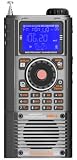
- WIDE FREQUENCY COVERAGE: Receives FM (64-108MHz), MW (520-1710kHz), SW (2.3-30MHz), AIR (118-138MHz), CB (25-28MHz), VHF (20-250MHz), UHF (250-999MHz), and WB (162.4-162.55MHz) bands
- SSB CAPABILITY: Shortwave mode supports AM, LSB, and USB demodulation with BFO fine-tuning adjustment for clear single sideband reception
- BLUETOOTH & MEDIA PLAYBACK: Features Bluetooth 5.2 connectivity and TF card support for music playback, plus app-based intelligent remote control
- LARGE STATION MEMORY & DISPLAY: Stores up to 1,400 radio stations with an STN LCD blue-backlit screen offering wide viewing angle and clear outdoor visibility
- VERSATILE FEATURES: Includes squelch control, bandwidth settings, internal recording, alarm and sleep timer, 6 EQ sound effects, and numeric keypad for direct frequency entry
- Detector behavior: waveform sensitivity, input range, linearity, and frequency coverage.
- Gain-control behavior: VGA or attenuator range, control law, voltage span, linearity, and frequency coverage.
- Loop behavior: target level and detector headroom, control polarity, bandwidth, acquisition and settling, stability, and response to overload.
- Receiver performance: modulation tracking or gain pumping, noise, distortion, layout, power, and component availability.
Analog Devices says the AD8318 used in AN-1507 covers 1 MHz to 8 GHz and has a 60 dB detection range; the note also attributes ±0.5 dB temperature stability to that detector. Those are AD8318 specifications in the application-note context, not guarantees for a complete AGC loop. AN-1507’s example uses the AD8318 and an ADL5330, a transmit-oriented VGA; it suggests the AD8368 for receive applications up to 800 MHz. The example reports control over just under the VGA’s 60 dB range and ±0.5 dB conformance over the top 40 dB of output power under its specified conditions. These results should not be assumed for another circuit. Analog Devices AN-1507.
Why loop speed and detector headroom matter
The loop filter governs how quickly AGC responds and contributes to stability. In AN-1507, the detector’s CLPF capacitor is used to set loop bandwidth and ensure stability; increasing the integration capacitor in that example slows the response. Those relationships explain the design trade-off, but they do not establish a capacitor value or response time for another detector, controller, or receiver.
Rank #2

- Turn your computer, phone or tablet into a radio scanner/ham radio receiver that can receive nearly all RF signals! Compatible with Windows, Mac OS, Linux, and Android
- NESDR SMArt RTL-SDR v5 can be used for the reception of broadcast AM radio, broadcast FM radio, shortwave radio, CB radio, public security radio, trunked radio, air traffic control, ACARS (plane-ground communications), ADS-B (plane tracking), AIS (ship tracking), POCSAG (pagers), NOAA and GOES weather satellites (weather images), weather balloons, radiosondes, DAB radio, DVB-T video, Inmarsat, Iridium, and so much more!
- The best-performing low-cost RTL-SDR available anywhere! Compared with RTL-SDR v3, HF SNR is improved by up to 15dB, VHF & UHF SNR is improved by up to 6dB, tuning accuracy is improved by an average of 4x, and the frequency range is expanded all the way down to 100kHz
- v5 has a frequency capability of 100kHz to 1.75GHz and up to 3.2MHz of instantaneous bandwidth. HF reception below 25MHz is accomplished with direct sampling and requires a suitable antenna. We recommend using a Balun One Nine to make a DIY long wire or dipole antenna (sold separately, product ID B08HGSYB7R or B00R09WHT6)
- Though the direct sampling implementation of NESDR SMArt v5 is much better than any other RTL-SDR, we still recommend using an upconverter like the Ham It Up for a more fulfilling HF experience (sold separately, product ID B076CYK8XZ)
Do not set the normal operating point at the detector’s maximum. The detector needs upward headroom to sense a stronger input and provide a restoring error. Detector output swing may also be unequal above and below equilibrium, so apparent attack and decay speeds can differ. Dana Whitlow notes in Analog Devices’ 2006 receiver AGC seminar: “Note that there will generally be unequal amounts of room for the detector output to swing up from the design equilibrium level as opposed to down, which will make the apparent attack and decay speeds of the loop differ.”
Quick Recap
Best Value

- RX frequencies: 100kHz-1309.995MHz
- Built-in audio low pass filter
- 150mW loud audio with internal speaker
- Priority watch function with priority beep function
- Automatic LCD backlight
Rank #4

- The GOOZEEZOO ATS-20+ Radio boasts a versatile frequency range with sound bandwidth filters set at 0.5, 1, 1.2, 2.2, 3, and 4 kHz, accommodating an extensive array of 22 pre-configured channels spanning both commercial and amateur radio frequencies.
- High Quality Sound: The shortwave ham radio comes with a high-quality front speaker that produces excellent audio, providing you with an listening experience
- Play it Anywhere: The sw radio receiver is a highly portable device that can be taken anywhere for various needs, thanks to its compact dimensions of 3.6 * 3.2 * 1.5 inch. Support a 3.5 mm stereo earphone jack for private listening (stereo earphones not included). And the handheld radio shell is made of aluminum alloy, which makes it strong and wear-resistant, ensuring its durability and longevity over time
- Excellent Reception: With the high sensitivity radio, users can enjoy stable performance and reception across all bands, providing more choices of radio channels to listen to. The Si4732 chip is known for its high sensitivity and selectivity, which ensures that the multi band ham radio receiver can pick up signals from even the weakest of stations without noise
- Technology: Digital Signal Processing (DSP) technology can be used to enhance the selectivity, signal-to-noise ratio, and anti-interference ability of radio signals. For those who primarily listen to FM channels, using a ham radio receiver with DSP technology can provide significant benefits. The PCB retains the SI4735 package, can replace the chip by yourselves, and the software is compatible
Rank #3

- A digital portable receiver with comprehensive radio frequency coverage including AM, FM, longwave, shortwave, and single side band
- Adopts modern DSP digital demodulation technology as well as synchronized detection for enhanced and unparalleled reception sensitivity, selectivity, and anti-image interference capability across the bands
- A premium full-range 8 ohms / 250 mW speaker delivers loud, rich, crispy, dynamic and distortion-free sound for utmost entertainment experience, a 3.5 mm stereo earphone jack for private listening (stereo earphones included)
- Other convenient features include an alarm clock; a sleep timer of up to 120 minutes; external antenna input; 3.5mm audio output; 850 memories for easy access to frequently listened stations; keylock function for preserving settings
- Latest Updated Firmware Version 3307
What published AGC examples can—and cannot—tell you
| Example | Topology and reported conditions | How to use it |
|---|---|---|
| ADI AN-934 | Low-frequency example using an AD8336 VGA, AD736 RMS-to-DC converter, AD8551 op amp, and ADP3339 reference. It controls a 60 dB input span, from 5 mV p-p to 5 V p-p, to a 250 mV p-p output. | Useful for understanding the roles of the VGA, detector, reference, and comparison circuit; it is low-frequency/audio-oriented, not a general RF receiver prescription. ADI AN-934. |
| ADI AN-1507 | RF log-detector/VGA feedback example: an output sample passes through a coupler and attenuation to an AD8318 detector; a DAC provides the setpoint, and detector error controls the ADL5330 gain pin. The note reports control over just under the VGA’s 60 dB range and ±0.5 dB conformance over the top 40 dB of output power under the stated example conditions. | Shows a practical closed-loop arrangement and a receive-oriented VGA alternative, but its results and component pairings are specific to the note’s setup. ADI AN-1507. |
| ADI CN-0390 | Microwave loop combining an ADL6010 envelope detector, HMC985A VVA, HMC635 amplifier, and op-amp integrator. The design covers 20 GHz to 37.5 GHz; ADI describes performance as very good from 20 GHz to 30 GHz and says total gain falls off above 30 GHz. Loop closure is documented only while VVA control remains within its operating span. | A microwave instrumentation or radar example, not a universal communications receiver circuit. ADI CN-0390. |
| Whitlow, ADI Wireless Seminar Chapter VIII (2006) | A 380 MHz IF example using an AD8367 VGA and AD8361 RMS detector. Under its stated 18 dB peak-to-average modulation and 5 V supply assumptions, it selects an average VGA output of −12 dBm, equivalent to 112 mV RMS into an approximately 200 Ω total load, and develops a 200 Hz small-signal loop-bandwidth example. | Illustrates receiver-specific level and loop decisions. The output level and bandwidth belong to those assumptions, and the chapter treats acceptable gain pumping as an engineering judgment rather than a universal threshold. ADI Wireless Seminar Chapter VIII. |
What to test before relying on the AGC
- Sweep input level and frequency to find where regulation begins and where detector or gain-control limits prevent it.
- Measure steady-state output versus input and confirm the result against the intended target and allowed variation.
- Apply both positive and negative input steps; check attack, decay, settling, and recovery from overload.
- Test the actual modulation to detect gain pumping or unwanted tracking of signal content.
- Check stability, noise, and distortion across operating conditions, not only at the nominal level.
Product prices and availability are accurate as of the date/time indicated and are subject to change. Any price and availability information displayed on Amazon at the time of purchase will apply.
Do these 3 things before closing this tab:
1Clear out junk files and repair common Windows errors2Fix the driver behind crashes, sound loss and screen glitches3Repair Windows errors before they cause bigger problems
