
Recommended Free Tools
An industrial analog output converts a controller’s command into an electrical signal for a compatible actuator or other receiving device. Choose between signals such as 4–20 mA and 0–10 V by matching the receiver, wiring conditions, electrical load, and controller I/O hardware—not by assuming one signal type is always better.
What an industrial analog output does
A programmable logic controller (PLC) or remote I/O system calculates a command, then an analog output module produces a corresponding current or voltage. The receiving device—such as a compatible actuator or drive input—interprets that signal as a command. For example, a receiver configured for 4–20 mA cannot be assumed to accept 0–10 V; the output type and range must match the receiver’s input specification.
The module’s output range also matters. A command mapped to 0–10 V has different electrical meaning from one mapped to 1–5 V or 4–20 mA. Confirm how the controller’s configuration scales the process value into the selected output range and how the receiver interprets that range.
4–20 mA vs. 0–10 V: how to choose
| Consideration | 4–20 mA current signal | 0–10 V voltage signal |
|---|---|---|
| Receiver compatibility | Use when the receiving input is specified for 4–20 mA. | Use when the receiving input is specified for 0–10 V. |
| Cable and electrical conditions | Current-loop signaling can be useful on longer runs and in electrically noisy settings. The loop supply must cover the total voltage drop, including the receiver’s load. | Suitability depends on the receiver and module load limits. Voltage transmission is more susceptible to signal amplitude loss from cable resistance than current-loop transmission. |
| Fault interpretation | The 4 mA lower endpoint is distinct from zero current, and some implementations use below-range or above-range values to indicate faults. Thresholds are not identical across manufacturers. | Interpretation of an out-of-range or failed signal depends on the module and receiver; verify their documented behavior. |
| Module constraints | Check the maximum supported current load (also called burden) and available loop voltage. | Check the minimum permitted voltage load and wiring conditions. |
The International Society of Automation describes 4–20 mA as a signaling range for analog data transmission in instrumentation and control under ANSI/ISA-50.00.01-1975 (R2012). ISA’s standards information also notes that some implementations use values below 4 mA or above 20 mA for fault indications; do not assume a universal threshold.
Free tools Windows power users keep installed
One-click scans. No signup required.
#1 Best Overall

- Signal Isolator:Input and output,ultra-thin, intelligent and isolated safety net. Channel configuration:1 input and 2 outputs.Standard guide rail slot, used in conjunction with guide rails, facilitates dense installation and saves space
- Specifications: DC signal conditioner supply voltage: DC 10V ± 10%; rated power consumption: 1W; response time: 100MS; dielectric strength: 2000V AC / 1MIN; input impedance: 50Ω; ambient temperature: -20 - 55 (℃); size: 3.93 × 0.88 × 4.5 Inches.
- Performance: Input/output signal isolation: effectively removes electromagnetic interference during signal transmission. Input signal/power isolation: effectively filters out noise in the signal, greatly improving signal stability
- Widely Used: Signal converters are widely used in industrial equipment, such as large motors, medical equipment,Power system,mechanical equipment,etc.
- Product Material and Safety: Current signal conditioner is made of high quality electronic components with high precision,High precision, low temperature drift
In a current loop, current remains consistent along the conductor when the source has sufficient voltage to overcome the total loop drop. The receiver’s termination resistor converts current to a voltage for measurement. Analog Devices explains that this can avoid the signal-amplitude loss associated with voltage transmission over long cables, while also identifying long-distance transmission, fault detection, inexpensive two-wire cabling, and lower EMI sensitivity as potential advantages—not immunity from noise or wiring faults. See its technical article on DACs and current loops for the circuit principle.
Why module specifications matter
Signal labels alone do not establish that an output module can drive a particular receiver. Channels, selectable ranges, load capability, accuracy, resolution, response time, isolation, diagnostics, fault-state behavior, wiring, environmental limits, and PLC-family compatibility can differ by exact catalog number.
Rank #2

- Signal Isolator:Input and output,ultra-thin, intelligent and isolated safety net. Channel configuration: 2 input and 2 output.Standard guide rail slot, used in conjunction with guide rails, facilitates dense installation and saves space
- Specifications: DC signal conditioner supply voltage: DC 24V ± 10%; rated power consumption: 1W; response time: 100MS; dielectric strength: 2000V AC / 1MIN; input impedance: 50Ω; ambient temperature: -20 - 55 (℃); size: 3.93 × 0.88 × 4.5 Inches.
- Performance: Input/output signal isolation: effectively removes electromagnetic interference during signal transmission. Input signal/power isolation: effectively filters out noise in the signal, greatly improving signal stability
- Widely Used: Signal converters are widely used in industrial equipment, such as large motors, medical equipment,Power system,mechanical equipment,etc.
- Product Material and Safety: Current signal conditioner is made of high quality electronic components with high precision,High precision, low temperature drift
| Example module | Documented outputs and channels | Other model-specific details |
|---|---|---|
| Rockwell Automation 5034-OF4 | Four channels; ranges include ±10 V, 0–10 V, 0–5 V, 0–20 mA, and 4–20 mA. | Rockwell lists 16-bit resolution for the stated unipolar voltage ranges and current range; calibrated accuracy is 0.10% of full scale at 25 °C and 0.2% over the full temperature range. Minimum voltage load: 3000 Ω. Maximum current load: 500 Ω. These are this module’s published specifications, not general values for analog outputs. |
| Rockwell Automation 5069-OF4 | Four voltage or current outputs; listed ranges include 0–10 V and 4–20 mA. | Its resolution, response, wiring, and platform details are specific to this model. Rockwell marks this model unsuitable for safety functions; that qualification should not be generalized to other modules. |
| Siemens ET 200SP AQ 2xU/I HF (6ES7135-6HB00-0CA1) | Two-channel voltage/current module; the January 2025 manual lists ±10 V, ±5 V, 0–10 V, 1–5 V, ±20 mA, 0–20 mA, and 4–20 mA. | Configuration codes and substitute-value ranges are specific to this module and its manual. |
These examples show why a buyer should compare specifications rather than infer capability from “analog output” or a manufacturer’s product family. Published figures apply only to the named model and conditions documented by its manufacturer.
Independent reader supportYour contribution helps us test, update, and keep practical guides available for everyone.Selection checklist
- Confirm the receiving input. Read the receiver’s documentation for supported signal type, range, input impedance or current burden, scaling, and behavior at or beyond the range endpoints.
- Match the signal and range. Select a module output that supports the receiver’s exact range—for example, 4–20 mA or 0–10 V—and verify controller scaling and any required engineering units.
- Check electrical load and wiring. For current loops, account for the receiver, cable, and other loop drops and confirm the source has enough voltage. For voltage outputs, verify the module’s load limit and the receiver’s input requirements. Follow the manufacturer’s wiring diagram.
- Check channel count and performance. Confirm the number of outputs, accuracy, resolution, response time, and environmental ratings against the application’s requirements.
- Review isolation, diagnostics, and fault behavior. Determine whether the module detects open wires or short circuits, what output it applies after a fault or controller-state change, and how the receiver treats fault-range values.
- Verify platform compatibility. Check the exact catalog number, PLC or remote I/O family, configuration method, terminal requirements, and applicable manual before purchase or installation.
Use the current manufacturer manual and wiring diagram for final engineering decisions. This overview does not replace the equipment documentation, site electrical design, or applicable safety requirements; verify product-specific safety status before considering any module in a safety-related application.
What’s actually slowing this PC down?
Pick the symptom - the matching free tool is one click away.
Quick Recap
Best Value
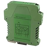
- Analog Signal Isolator with single input with dual output
- Zero and span adjustment for precise calibration
- 3-Way isolation to eliminate interference
- DIN rail mounting and pluggable terminals for quick installation Screw Clamp terminations for easy wiring
Rank #4

- (2902003) 3-WAY SIGNAL CONDITIONER
- FOR THE ELECTRICAL ISOLATION OF ANALOG SIGNALS. INPUT SIGNAL: 4 MA ... 20 MA
- OUTPUT SIGNAL: 0 V ... 10 V
- PUSH-IN CONNECTION TECHNOLOGY
- WITH PLUG-IN CONNECTION TECHNOLOGY
Rank #3
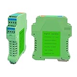
- Signal Isolator:Input and output,ultra-thin, intelligent and isolated safety net. Channel configuration: 1 input and 1 output.Standard guide rail slot, used in conjunction with guide rails, facilitates dense installation and saves space
- Specifications: DC signal conditioner supply voltage: DC 24V ± 10%; rated power consumption: 1W; response time: 100MS; dielectric strength: 2000V AC / 1MIN; input impedance: 50Ω; ambient temperature: -20 - 55 (℃); size: 3.93 × 0.88 × 4.5 Inches.
- Performance: Input/output signal isolation: effectively removes electromagnetic interference during signal transmission. Input signal/power isolation: effectively filters out noise in the signal, greatly improving signal stability
- Widely Used: Signal converters are widely used in industrial equipment, such as large motors, medical equipment,Power system,mechanical equipment,etc.
- Product Material and Safety: Current signal conditioner is made of high quality electronic components with high precision,High precision, low temperature drift
Product prices and availability are accurate as of the date/time indicated and are subject to change. Any price and availability information displayed on Amazon at the time of purchase will apply.

