
You can use a DS1307 with an ESP8266 for timekeeping, 56 bytes of battery-backed general-purpose SRAM, and a programmable square-wave signal. In an Arduino sketch, choose I²C pins for your specific ESP8266 board with Wire.begin(SDA, SCL). For the DS1307’s open-drain SQW/OUT pin, use a pull-up voltage that is safe for the ESP8266 input—do not pull it up to 5 V.
What the DS1307 adds to an ESP8266 project
The DS1307 is an I²C real-time clock/calendar. It keeps time with a 32.768 kHz crystal and has a separate backup supply input so the clock can continue when the main supply is absent. It also includes 56 bytes of battery-backed general-purpose SRAM; Analog Devices describes the RAM as supporting unlimited writes. See the DS1307 product information and the Rev. 5 datasheet, dated March 23, 2015.
Those features serve distinct purposes: the clock/calendar maintains date and time, the SRAM stores small amounts of data across loss of the main supply, and SQW/OUT can supply a timing signal or a static output. A module can package the chip with supporting parts, but module layouts and provisions vary.
Choose I²C pins for your ESP8266 board
The ESP8266 Arduino Core lets a sketch set I²C pins by calling Wire.begin(sda, scl). Its documentation gives GPIO 4 for SDA and GPIO 5 for SCL as defaults, and GPIO 0 for SDA and GPIO 2 for SCL as an ESP-01 example. These are not interchangeable recommendations for every board: check the board’s pin mapping and startup constraints before wiring. Consult the ESP8266 Arduino Core Wire documentation.
Outdated Drivers Are Slowing You Down
One free scan finds every outdated or missing driver and matches the right update for your exact hardware.Free scan · exact hardware matchWindows Errors? Fix Them Before They Spread
Repair common Windows errors and clear accumulated junk for a smoother, more stable PC - no reinstall needed.Free scan · no reinstall#1 Best Overall
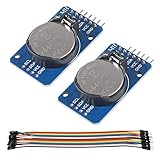
- DS3231 16-pin memory chips - AT24C32 ,extremely accurate I2C real-time clock (RTC), with an integrated temperature-compensated crystal oscillator (TCXO) and crystal.
- Highly accurate RTC completely manages all timekeeping functions.The device incorporates a battery input, disconnect the main power supply and maintains accurate timekeeping.
- Integrated oscillator improve long-term accuracy of the device and reduces the number of components of the production line.
- Provides two configurable alarm clock and a calendar can be set to a square wave output. Address and data are transferred serially through an I2C bidirectional bus.
- A precision temperature-compensated voltage reference and comparator circuit monitors the status of VCC to detect power failures, provide a reset output. In addition, RST pin is monitored as generating a μP reset.
For example, after confirming that GPIO 4 and GPIO 5 are suitable on your board, initialize I²C with:
Wire.begin(4, 5); // SDA, SCLConnect the RTC’s SDA and SCL to those selected pins, and connect the grounds. The exact power and pull-up wiring depends on the particular DS1307 circuit or module; inspect its documentation rather than assuming every board is wired alike.
Rank #2

- DS3231 16-pin memory chips - AT24C32 ,extremely accurate I2C real-time clock (RTC), with an integrated temperature-compensated crystal oscillator (TCXO) and crystal.
- Integrated oscillator improve long-term accuracy of the device and reduces the number of components of the production line.
- Provides two configurable alarm clock and a calendar can be set to a square wave output. Address and data are transferred serially through an I2C bidirectional bus.
- Highly accurate RTC completely manages all timekeeping functions.The device incorporates a battery input, disconnect the main power supply and maintains accurate timekeeping.
- A precision temperature-compensated voltage reference and comparator circuit monitors the status of VCC to detect power failures, provide a reset output. In addition, RST pin is monitored as generating a μP reset.
Wire the DS1307 and protect the ESP8266 input
Bare chip and module differences
A bare DS1307 circuit uses a 32.768 kHz crystal and a separate backup supply input, as specified in the DS1307 datasheet. A module may include some of these supporting components, but do not assume it includes a functioning crystal, pull-ups, a battery, or a particular signal voltage. Check the module’s documentation and inspect its actual connections before applying power.
SQW/OUT pull-up voltage
The DS1307 datasheet specifies SQW/OUT as an open-drain output that requires an external pull-up. Although the datasheet permits a pull-up as high as 5.5 V for the RTC output, that does not make an ESP8266 GPIO 5 V tolerant. Choose a pull-up voltage and resistance compatible with both the RTC circuit and the ESP8266 input; do not connect a 5 V pull-up directly to an ESP8266 GPIO. Check the Espressif ESP8266EX datasheet for host-chip electrical specifications.
What’s actually slowing this PC down?
Pick the symptom - the matching free tool is one click away.
Rank #3

- 【Product】DS1307 I2C real time clock chip, 24C32 32K I2C EEPROM memory, the DS1307 is accessed via the I2C protocol.
- 【Advantage】Solve the problem DS1307 with backup battery can not read and write, In battery backup mode, Low power consumption, Automatic brownout detection and switching circuit.
- 【Feature】It can count seconds, hours, minutes, days of the month, months, and days of the week, and has the function of leap year compensation. Yearbook Online 2100.
- 【Multi-function】Connected to the clock pin of DS1307 to provide clock signal for microcontroller. Can be cascaded to other I2C devices.
- 【Note】Using 2032 rechargeable lithium battery, And with charging circuit. After fully charged, it can provide DS1307 timing for 1 year. Note:This product kit does not come with a battery.
Configure the square-wave output
The DS1307 provides four selectable square-wave frequencies: 1 Hz, 4 kHz, 8 kHz, and 32 kHz. When square-wave output is disabled, the control behavior also allows the pin to act as a static output. The available setting therefore depends on whether your project needs a periodic signal or a fixed output. The details are in the DS1307 datasheet; the Adafruit RTClib SQW example illustrates off, constant-on, and the four square-wave modes.
Driver APIs differ, so follow the library you selected rather than assuming a particular call or enum name. For example, the esp-idf-lib DS1307 driver documentation describes functions for configuring the output mode and frequency.
Rank #4

- Two wire I2C interface ⊙Hour : Minutes : Seconds AM/PM ⊙Day Month, Date - Year ⊙Size: 28x25x10mm ⊙Leap year compensation ⊙Accurate calendar up to year 2100 ⊙DS1307 based RTC with LIR2032 battery (Battery include) ⊙1Hz output pin ⊙56 Bytes of Non-volatile memory available to user ⊙The module comes fully assembled and pre-programmed with the current time. ⊙This is the DS1307 Real Time Clock Module For Arduino AVR ARM PIC. ⊙The DS1307 is accessed via the I2C protocol.
- This is the DS1307 Real Time Clock developed by one of our designer waiman. The module comes fully assembled and pre-programmed with the current time (ok, so it's our current time - MST). The included Lithium coin cell battery (CR1225 41mAh) will run the module for a minimum of 9 years (17 years typical) without external 5V power. The DS1307 is accessed via the I2C protocol.
- Package included:Ximimark 5Pcs I2C RTC DS1307 AT24C32 Real Time Clock Module for AVR ARM PIC SMD for Arduino
- Thank you very much for shopping in our store. Please feel free to contact us if you have any questions.
Use the 56-byte SRAM for small persistent values
The DS1307’s battery-backed RAM is general-purpose storage, not a guarantee that an application’s saved data is valid or internally consistent. The esp-idf-lib driver documents byte-range access at offsets 0 through 55. Keep your data within that range and define your own layout—for example, reserve bytes for a format version and validation value alongside the data. Those checks are application design choices; the DS1307 does not prescribe a storage format.
Because the RAM is small, it suits compact settings or state rather than large logs. The manufacturer documents 56 bytes and unlimited writes in its product information; the driver’s RAM documentation describes the usable offsets.
Quick wins for a faster PC:
Clear out junk files and repair common Windows errorsFree Scan →Fix the driver behind crashes, sound loss and screen glitchesFind Drivers →Repair Windows errors before they cause bigger problemsFix Now →Quick Recap
Best Value

- DS3231 16-pin memory chips - AT24C32 ,extremely accurate I2C real-time clock (RTC), with an integrated temperature-compensated crystal oscillator (TCXO) and crystal.
- Integrated oscillator improve long-term accuracy of the device and reduces the number of components of the production line.
- Provides two configurable alarm clock and a calendar can be set to a square wave output. Address and data are transferred serially through an I2C bidirectional bus.
- Highly accurate RTC completely manages all timekeeping functions.The device incorporates a battery input, disconnect the main power supply and maintains accurate timekeeping.
- A precision temperature-compensated voltage reference and comparator circuit monitors the status of VCC to detect power failures, provide a reset output. In addition, RST pin is monitored as generating a μP reset.
Check these details before choosing or wiring hardware
- ESP8266 board: Confirm the available SDA/SCL pins and any boot-time restrictions for those GPIOs.
- RTC construction: Establish whether you have a bare chip or a module, and whether the required crystal and backup supply are present.
- Pull-ups: Determine whether the I²C lines and SQW/OUT already have pull-ups, what voltage they use, and whether that voltage is safe for the ESP8266.
- Module features: Verify that a battery is included and usable, and that SQW/OUT is exposed if your project needs it.
- Output requirement: Choose a supported frequency or static output mode that matches the circuit’s purpose.
Product prices and availability are accurate as of the date/time indicated and are subject to change. Any price and availability information displayed on Amazon at the time of purchase will apply.

