
On Cortex-M0 and Cortex-M0+, Sleep and Deep Sleep are architectural low-power modes, not fixed current-consumption settings. The SLEEPDEEP bit in the System Control Register selects which mode a wait instruction requests: clear for Sleep, set for Deep Sleep. What Deep Sleep actually powers down—and how much current or wake latency you get—depends on the specific microcontroller and board.
Sleep vs. Deep Sleep: what changes?
Both modes stop the processor from executing while it waits. The distinction is how deeply the surrounding system is asked to reduce power. In the System Control Register, SLEEPDEEP clear selects Sleep; set selects Deep Sleep.
| Mode | Architectural selection | What it means in practice |
|---|---|---|
| Sleep | SLEEPDEEP is clear |
The processor clock normally stops. The surrounding MCU decides which other clocks and peripherals continue running. |
| Deep Sleep | SLEEPDEEP is set |
A request to the surrounding system for deeper shutdown. Depending on the MCU, this may stop the system clock or switch off resources such as the PLL and flash; it does not guarantee those actions on every device. |
Arm’s Cortex-M0 Devices Generic User Guide states that implemented sleep modes are implementation-defined. Consequently, the core name alone does not tell you the current draw, retained state, available wake sources, or time to resume. Those are properties of the MCU implementation and its configuration.
How WFI and WFE enter low-power states
WFI: wait for an interrupt
WFI (Wait For Interrupt) stops instruction execution and enters the selected sleep mode until a qualifying interrupt or debug event occurs. For typical interrupt-driven idle code, CMSIS provides __WFI(). Whether a particular pending or enabled interrupt qualifies depends on the interrupt configuration and architecture rules, so verify the behavior for your MCU and firmware setup.
Recommended Free Tools
#1 Best Overall

- 【High-Performance Dual-Core Architecture】 Dual-core Cortex M0+ processor; 133MHz clock speed; 16MB onboard flash memory; Suitable for complex embedded systems and real-time applications
- 【Easy Integration with Popular Tools】 Compatible with for Arduino IDE; supports for Raspberry Pi and STM32 development boards; simple setup for rapid prototyping and project development
- 【Low-Power Design with Reliable Power Options】 3.3V operating voltage; 2000mAh battery support; micro USB interface for programming and power; recommended external 3.3V supply for high-power usage
- 【Robust Connectivity and Expandability】 Includes GPIO pins; 3V3 output for peripheral devices; USB-C compatible for stable and fast data transfer
- 【Engineered for Stability and Longevity】 Designed for continuous operation; low power consumption in sleep mode; suitable for educational projects and hobbyist electronics
WFE: wait for an event
WFE (Wait For Event) uses the processor’s event register. If that register is clear, WFE waits for an event; if it is set, WFE clears it and returns immediately. CMSIS provides __WFE() for event-driven waits. A WFE loop must account for this clear-and-return behavior: an event already recorded can make the instruction return without sleeping.
Review SEVONPEND when choosing WFE. This setting affects whether a pending interrupt can generate an event, including cases where the interrupt is disabled. Do not assume WFE and WFI react identically to the same interrupt state.
Rank #2

- 【High-Speed Dual-Core Processor】 Dual-Core ARM Cortex-M0+ at 120MHz; 4MB Flash memory; 256KB RAM for complex applications
- 【Easy Integration with Popular Development Platforms】 Compatible with for Arduino IDE and for Raspberry Pi; supports USB programming for quick setup
- 【Robust GPIO and PWM Support】 Multiple GPIO pins and PWM output for motor control and sensor interfacing
- 【Low-Power Operation with Stable Performance】 3.3V power supply; 1.8µA sleep mode current; reliable in various Workplaceal conditions
- 【Black PCB Design for Professional Projects】 Black color PCB for clean appearance; suitable for embedded systems and educational use
Configure Deep Sleep safely
SLEEPDEEP selects the architectural class; it does not configure the MCU’s regulator, clocks, peripherals, or memory retention for you. Apply the vendor’s required peripheral and power setup before requesting Deep Sleep, and restore any changed system state after wake.
- Read the exact MCU reference manual. Identify the vendor’s low-power mode corresponding to the core’s Deep Sleep request, along with its required regulator, clock, and power-control settings.
- Choose what must remain available. Configure memory retention and the peripheral or interrupt sources that need to wake the device. Confirm which SRAM banks, timers, clocks, flash, and other peripherals survive the selected mode.
- Prepare the system before sleeping. Put peripherals into their required low-power states and configure vendor-specific controls before setting
SLEEPDEEP. - Use the wait instruction suited to the design. Use CMSIS
__WFI()for interrupt-driven idle or__WFE()for event-driven waits, with the event-register behavior andSEVONPENDsetting in mind. - Restore and verify after wake. If the vendor mode changes clocks or other system state, re-establish what the application requires before using affected peripherals or timing services.
Sleep-on-Exit for interrupt-driven firmware
Sleep-on-Exit can return the processor to Sleep or Deep Sleep when an exception handler finishes. It suits firmware that has no foreground work between interrupt handlers: after servicing an event, the core can wait again rather than run an idle loop. Before enabling it, ensure that the application does not need foreground code after the handler returns.
Free tools Windows power users keep installed
One-click scans. No signup required.
Rank #3

- The Raspberry Pi Pico is a beginner-friendly microcontroller board that uses MicroPython to give you a taste of the Internet of Things and microcontrollers. The RP2040 is a well-designed microprocessor that can be utilized in almost any Internet of Things project. It has enough power to complete the task quickly.
- 【Raspberry Pi RP2040 Microcontroller】Raspberry Pi Pico features Dual-core ARM Cortex M0+ processor, flexible clock running up to 133 MHz. With 264KB of SRAM, and 2MB of on-board Flash memory.Supports up to 16 MB of off chip flash memory via a dedicated QSPI bus
- 【Multiple Software Support】Pico has rich and complete software support, it comes with a complete Rasberry Pi official C/C++ SDK, Micropython SDK.The programming and burning of Pico need to be carried out on the computer. Supported operating systems and computers include:Raspberry Pie with Raspberry Pi OS,Other platforms equipped with Debian based Linux system Computer with MacOS, Computers with Windows, etc.
- 【Rich Hardware Interface】Raspberry Pi Pico has 30 GPIO pins, 4 pins for analog signal input and 26 × multi-function GPIO pins, 2 × SPI, 2 × I2C, 2 × UART, 3 × 12-bit ADC, 16 × controllable PWM channels.USB 1.1 supported by host and device, The installation mode can be flexibly selected by users to facilitate welding with other development boards.
- 【Build Project in Tiny Size】Only 2.1cm*5.1cm ( as small as your thumb). Pico has been designed to use either soldered 0.1" pin-headers or can be used as a surface-mountable 'module'.
WIC, wake latency, and timing
An implementation may include an optional Wakeup Interrupt Controller (WIC). In Deep Sleep, a WIC can allow much of the core to be power-gated while still detecting a wake-up interrupt. That deeper shutdown can add restoration time; the implementation may also stop SysTick. Check the MCU documentation if wake latency or timer continuity matters, and validate the behavior in the selected mode.
Why current may remain high in Deep Sleep
Setting SLEEPDEEP only requests the architectural mode. The MCU may still draw substantial current if its implementation or configuration leaves power-hungry resources active, or if the measurement includes board-level loads. Diagnose the actual device and board rather than treating the core label as a current specification.
Rank #4
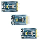
- 【High-Performance ARM Cortex-M0 Core】STM32F030F4P6 development board features a 48MHz ARM 32-bit Cortex-M0 processor; 16KB Flash and 4KB SRAM with hardware parity; Suitable for embedded projects and sensor acquisition.
- 【Advanced Communication Interfaces】Equipped with two USARTs, two SPIs, and two I²Cs including SMBus support; compatible with LabVIEW, MATLAB, and STM32; supports up to 18Mbps data transfer rate.
- 【Precision ADC and Low-Power Design】12-bit ADC with 1.0μs conversion time and 11 input channels; sleep mode current as low as 1.8μA; suitable for battery-powered applications and long-term monitoring systems.
- 【Reliable Reliability and Stability】Built-in hardware watchdog and power monitoring circuit; operates in -40°C to 85°C range; resistant to interference and stable under varying conditions.
- 【Easy Integration and Debugging Support】Includes SWD debug interface (PA13/PA14); supports J-Link and ST-Link programming; all GPIO and communication pins are available via 2.54mm headers for breadboard compatibility.
- Check the vendor mode mapping and setup. Confirm the intended MCU power mode is selected and all required regulator, clock, and power controls are configured.
- Find what remains powered. Use the reference manual to check clocks, PLL, flash, SRAM banks, timers, peripherals, and retention settings for that exact mode.
- Check wake sources and activity. Peripheral activity or repeated wake-ups can prevent the system from remaining in its deepest state for long.
- Account for the board. Regulators, sensors, interfaces, and other board circuitry can draw current independently of the processor’s low-power state.
- Measure representative firmware. Debugger attachment can perturb current or wake behavior. Compare measurements with and without debug hardware connected when practical, and use the MCU vendor’s prescribed measurement conditions.
Arm’s Cortex-M0 and Cortex-M0+ architecture documentation does not establish one universal Deep Sleep current or wake-latency value. Measure the exact MCU and board in the intended configuration; report the mode, retained resources, board setup, and measurement conditions alongside any result.
Independent reader supportYour contribution helps us test, update, and keep practical guides available for everyone.What to compare between Cortex-M0/M0+ microcontrollers
The core designation does not guarantee equivalent low-power behavior across MCUs. When choosing or evaluating devices, compare these implementation-level characteristics in their vendor documentation:
PC Slower Than It Used to Be?
A free scan shows the junk files, broken settings and background clutter dragging Windows down - then fixes them in one click.Free scan · Windows 10 & 11Outdated Drivers Are Slowing You Down
One free scan finds every outdated or missing driver and matches the right update for your exact hardware.Free scan · exact hardware matchQuick Recap
Best Value

- Raspberry Pi Pico: A tiny, fast, and versatile board built using dual-core Arm Cortex-M0+ processor (Comes with pinout card and stickers)
- Detailed Tutorial: Provides step-by-step guide with MicroPython, C and Processing (Java) Code (The download link can be found on the product box) (No paper tutorial)
- Example Projects: Each project has schematics, wiring diagrams, complete code and detailed explanations (Need extra items)
- Easy to Use: Just connect the board to your computer (installed IDE) with the USB cable to program it
- Get Support: Our technical support team is always ready to answer your questions
- Attainable current in the specific mode and the conditions under which it is specified.
- Wake latency and clock-restart behavior.
- SRAM and register retention options.
- Whether flash, system clocks, and PLL remain available or must be restored.
- Which peripherals and interrupt sources can wake the device.
- Regulator requirements and whether an optional WIC or vendor-specific retention controller is present.
- Debug behavior and any effect on low-power entry, wake, or measurement.
Product prices and availability are accurate as of the date/time indicated and are subject to change. Any price and availability information displayed on Amazon at the time of purchase will apply.

