
Quick wins for a faster PC:
Scan for outdated or missing drivers - takes under a minuteDriver Scan →Repair Windows errors before they cause bigger problemsFix Now →Fix the driver behind crashes, sound loss and screen glitchesFind Drivers →“Start-stop” can mean a machine control circuit or a vehicle system that switches the engine off at a stop. For industrial equipment, a basic start-stop circuit uses a momentary Start input, a normally closed Stop input and a relay or PLC latch—but that ordinary control circuit is not a substitute for safety-rated controls. For a vehicle, the design challenge is supporting frequent engine restarts without compromising battery, starter or charging-system compatibility.
First, identify which start-stop system you mean
The two uses share a name but solve different problems. An industrial circuit commands a machine to run or stop. An automotive system shuts off the engine during a traffic stop and restarts it when the driver is ready to move.
- Industrial controls: Design the run command, stopping behavior, safety functions and restart sequence.
- Automotive systems: Design or service components for repeated engine starts, including the battery, starter and charging system.
How to design an industrial start-stop control circuit
A conventional, non-safety relay circuit uses a momentary Start contact to energize a relay coil. A normally open auxiliary contact on that relay then holds the coil energized after the operator releases Start. A normally closed Stop contact sits in series with the coil; pressing Stop opens the circuit, de-energizes the relay and removes the run command. Unit Circuits describes this basic relay-latch sequence.
Define each control function
Write down what each control is meant to do before wiring or programming it. CDOE’s 2026 pushbutton guide describes momentary 1NO contacts for Start, momentary 1NC contacts for ordinary Stop, and a separate latching device for emergency stop.
#1 Best Overall

- This Momentary Push Button switch Warranty 1 years . If there are quality problems within 1 years, you can send us email. We will send you new ones .
- Button Color : Green Sign switch; contact Type : 1NO ; action Type : Momentary ;Ith : 10A; ui : 660V; screw terminal quantity : 2
- Button Color : Red Sign switch; contact Type : 1NC ; action Type : Momentary ;Ith : 10A; ui : 660V; screw terminal quantity : 2
- Overall Size(not include button) : 11x 7.2 x 6.5cm/ 4.3" x 2.83" x 2.5" (L*W*H); Button Diameter(Approx.):2.9cm/1.14"
- Weight : 200g; Package Content : 1 x Switch Box Station
| Function | Typical control behavior | Design implication |
|---|---|---|
| Start | Momentary command to request operation | It initiates the run latch; it should not be confused with a reset function. |
| Normal Stop | Momentary command that interrupts the run command | A normally closed contact is commonly used in a conventional control circuit. |
| Reset | Restores readiness after a fault or safety interruption | Reset should not itself initiate hazardous motion. |
| Emergency stop | Dedicated, latching safety-device function | It is not interchangeable with an ordinary momentary Stop pushbutton. |
Implement the run latch
For a basic relay circuit, place the Start contact and the relay’s normally open auxiliary holding contact in parallel, with the Stop contact in series with the relay coil. Pressing Start energizes the coil; the auxiliary contact maintains the command when Start is released. Pressing Stop opens the series path and releases the relay. This is a functional description, not a wiring design for a particular voltage, load or machine.
A PLC can implement the same operating idea with a run bit, but the logic should make interlocks, mode selection and fault handling explicit. A simple latch—whether in a relay or software—does not by itself provide a safety function.
Why ordinary Stop is often normally closed
In a conventional control circuit, a normally closed Stop contact opens when pressed. If a wire breaks or a connection fails in that series path, the circuit also opens and the run command drops out. CDOE explains this fail-safe rationale and why Stop and Start contacts are not interchangeable. This convention does not make the whole machine safety-rated; the complete circuit and its application still matter.
Rank #2
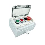
- IP67 WATERPROOF PROTECTION: With an IP67 protection rating, this industrial push-button control box is fully dustproof and highly water-resistant. Designed as an outdoor start-stop control box, it operates reliably in a wide range of harsh operating conditions.
- PROTECTIVE COVER DESIGN: Fitted with a flame-retardant, transparent PC spring-loaded hinge cover, it effectively prevents accidental activation of the start/stop button, selector knob and emergency stop switch; this anti-misoperation design significantly enhances safety in industrial operations.
- DURABLE CONSTRUCTION: This waterproof push-button switch box features an engineering-grade flame-retardant housing, a silicone waterproof seal and stainless steel fixing screws, ensuring a robust construction, reliable performance and a long service life.
- PUSHBUTTON SWITCH TYPE: The control box incorporates green/red self-resetting buttons, a two-position selector switch and a mushroom-head emergency stop switch. Each switch features a normally open/normally closed contact design, supports a maximum rated voltage of 500 V, and has an electrical life of 5 million cycles and a mechanical life of 500,000 cycles.
- COMPLETE PACKAGE:The set includes green and red push-button switches, a 2-position selector switch, an emergency stop switch, a waterproof switch box, positioning tabs, fixing screws, shock-absorbing rubber pads and an instruction manual. It comes with all necessary components and is easy to install.
Keep emergency stop, reset and restart behavior distinct
A normal Stop is an operating control. An emergency stop is a dedicated safety device with latching action and direct-opening contacts; an ordinary red momentary pushbutton is not a replacement. Button color alone does not establish that a safety function meets its required performance.
Set safety requirements from the hazard
Before choosing safety hardware, determine the hazards and the machine’s required safe state. The safety-related control system—not an individual pushbutton—must be designed for the required Performance Level (PLr), response time, diagnostics and validation. The ISO 13849 guidance cited here emphasizes assessing the complete safety-related system.
Document the operating modes, access points, stop time, reset location and conditions under which restart is permitted. These requirements determine the control architecture and verification work; they cannot be inferred from a generic start-stop diagram.
Rank #3

- Product Name: Start Stop Push Button Station; Ith : 10A;Ui : 600V;Uimp : 6KV; Action Type : Red Emergency Stop + Momentary Red Green Flat Button;
- Red Mushroom:Control Emergency Stop; Red STOP:1NC--Momentary Stop; Green START:1NO--Momentary Start;
- Rated Voltage Current : 240V 3A; Overall Size(Exclude Mushroom Head) : 150 x 68 x 64mm/5.9" x 2.7" x 2.5"(L*W*H);
- Shell Material : Plastic; Color : Black, White, Red ,Green;Net Weight : 268g;
- Package Content : 1pcs x Push Button Station
Make reset prepare, not start
Reset should restore readiness after the cause of a stop has been cleared. A separate Start command should initiate motion. In particular, clearing a guard or light curtain must not automatically restart hazardous movement if someone could remain exposed. As the safety guidance puts it, “reset prepares; start commands.”
Check abnormal and recovery cases
Validate the machine’s state and restart behavior under the conditions relevant to its risk assessment. Record what happens for cases such as:
- Power loss and return.
- Guard opening or light-curtain interruption.
- Emergency-stop activation and release.
- A faulted contactor or stuck reset input.
- Jam clearing, maintenance or other restricted operating modes.
Review the circuit and software, test faults, measure stop time where required, and document validation evidence. The acceptance criteria must come from the machine’s safety requirements, not from whether the Start/Stop sequence appears to work during normal operation.
Rank #4

- IP67 WATERPROOF PROTECTION: This JCNEtrwgy push-button switch box has an IP67 rating, offering complete protection against dust and water. Designed as a start-stop switch box, it is suitable for outdoor use and a wide range of harsh industrial environments.
- PROTECTIVE COVER DESIGN: Features a PC flame-retardant transparent cover with a spring hinge to shield buttons from accidental activation, enhancing operational safety in busy industrial settings.
- DURABLE CONSTRUCTION: Built with engineering-grade flame-retardant plastic housing, a silicone waterproof ring, and stainless steel fixing screws for long-lasting stability and reliable performance.
- PUSHBUTTON SWITCH TYPE: A self-resetting switch featuring one normally open and one normally closed contact, with a maximum rated voltage of 550 V (general-purpose), an electrical life of up to 5 million cycles, and a mechanical life of up to 500,000 cycles.
- COMPLETE PACKAGE: Includes a push-button switch, waterproof switch box, locating card, mounting screws, rubber particles, and an instruction manual for easy setup.
What changes in an automotive start-stop system?
In a vehicle, the engine shuts off when the car comes to a complete stop while the battery powers electrical components; the engine then restarts when the driver is ready to move. The U.S. Department of Energy describes that operating principle for start-stop systems.
The repeated cycling changes component demands. DOE identifies cold starting, fast charging, weight and service life as challenges for batteries used in these systems. HELLA says starting can load a battery by approximately 100 A in petrol engines and up to 400 A in diesel engines, and notes that start-stop vehicles use more powerful starters. These are source-reported approximate loads, not a universal battery-sizing specification for every vehicle.
Choose parts by vehicle compatibility, not the label alone
Do not select a replacement battery merely because it is marketed as “start-stop” or AGM. Check the vehicle’s specified battery group size and chemistry, capacity, polarity, mounting and charging-system requirements. Where applicable, confirm battery-management registration requirements. Starter and charging-system compatibility also matter; exact fitment is vehicle-specific.
What’s actually slowing this PC down?
Pick the symptom - the matching free tool is one click away.
Best Value

- Product Name: Push Button Switch; Model No.: KAO-5
- Material : Plastic, Metal(surface waterproof),which makes the product more strong and sturdy;Action Type : Latching;Ith: 10A;Voltage: AC 220/380V
- Main Color: Black,Red,Green;Product Function: Simple operation,only press the green button to start and the red button to stop.
- Net Weight: 256g;Overall Size (Approx.): 90 x 56 x 62mm / 3.5" x 2.2" x 2.4" (L*W*T)
- Package Content: 2 x Push Button Switch
KOBA’s 2023 catalogue claims “4x the battery life compared to regular MF batteries (for start stop vehicles)” and describes AGM features such as enhanced deep discharge, fast charging and cycle-proofing. Treat the four-times figure as that manufacturer’s comparison claim, not a guaranteed or universal result across vehicles and batteries.
What to compare before selecting or verifying a design
For an industrial circuit or automotive component, match the design to its real electrical, operating and environmental demands. The relevant checks differ by application:
| Check | Industrial control | Automotive start-stop |
|---|---|---|
| Electrical fit | Supply and coil/input load, contact ratings and minimum switching capacity. | Battery group size, chemistry, capacity, polarity, cranking capability and charging compatibility. |
| Duty and environment | Expected cycles, electrical and mechanical life, temperature, vibration, dust, washdown, chemicals, enclosure rating and glove use. | Repeated starts, cold-start demand, charging behavior, vibration and mounting requirements. |
| Safety and behavior | Safe state, required PLr, diagnostics, reset behavior, interlocks and prevention of unintended restart. | Vehicle-specific system and battery-management requirements; verify fitment for the vehicle. |
| Verification | Risk assessment, circuit and software review, fault testing, stop-time measurement and documented validation. | Confirm component specifications against the vehicle requirements and charging system. |
A low-cost relay module may be appropriate for a simple, non-safety control task if its electrical ratings and environment suit the application. It must not be treated as a safety-rated controller. For machinery, use safety components and an architecture selected against the risk assessment; for vehicles, use parts confirmed for the specific model and system.
Quick Recap
Product prices and availability are accurate as of the date/time indicated and are subject to change. Any price and availability information displayed on Amazon at the time of purchase will apply.

