
Quick wins for a faster PC:
Repair Windows errors before they cause bigger problemsFix Now →Scan for outdated or missing drivers - takes under a minuteDriver Scan →Clear out junk files and repair common Windows errorsFree Scan →NXP’s Pins Tool configures which peripheral function a microcontroller pin uses and generates pin-initialization code. In the historical Kinetis SDK workflow, the handoff files are pin_mux.c and pin_mux.h; current NXP guidance places the same workflow in MCUXpresso Config Tools. The tool handles pin routing—not the UART, GPIO, SPI, or I²C driver that uses the routed pin.
What pin muxing does—and what it does not do
A microcontroller pin can often serve more than one purpose: for example, GPIO, UART, I²C, or SPI. Pin muxing selects which supported function is connected to a physical pin. The available choices depend on the exact MCU and package, and not every apparently suitable pin can necessarily be used as planned.


Erich Styger’s 2016 tutorial describes the Pins Tool succinctly: “The pins tool does one single thing: pin muxing.” It configures pin assignment and electrical properties, then generates initialization code. It does not replace peripheral drivers, clock setup, middleware, or application behavior. Review the exact device documentation and board schematic before committing a PCB layout; a pin’s alternate-function list and board-level connections both matter. Read the original tutorial.
Configure pins with the NXP Pins Tool
- Start a configuration. Open the web or desktop Pins Tool and create a configuration for the target board or processor.
- Select the exact device and package. Choose the correct MCU/package data. In the historical desktop workflow, new device data could be downloaded, and configurations were saved as
.mexXML files. - Route the required functions. In the Pins view, select a physical pin and choose the desired peripheral function. Use the routed-pin list and visual highlights to check which selections were successfully routed.
- Check configuration details. Inspect register values and generated source in the tool’s views. Confirm that the selected pins and settings match the hardware design.
- Export and integrate the output. Export
pin_mux.candpin_mux.h, or update the corresponding files in a Kinetis SDK V2.0 project. The historical tool could export a ZIP that also included a.mexfile, or write files directly to a project.
Worked example: FRDM-K64F RGB LED pins
Styger’s example configures the FRDM-K64F’s three LED connections as GPIO outputs. The tutorial identifies the board’s MCU package as the MK64FN1M0VLL12 and says that package has 100 pins.
What’s actually slowing this PC down?
Pick the symptom - the matching free tool is one click away.
#1 Best Overall
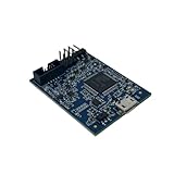
- POWERFUL PERFORMANCE: Featuring an NXP Kinetis K64 MCU with 120 MHz ARM Cortex-M4 core, 128 KB RAM and 1 MB Flash memory for robust processing.
- COMPREHENSIVE CONNECTIVITY: Integrated USB, Ethernet, CAN, UART, I2C, SPI and other interfaces enable seamless communication with various devices and networks.
- USER-FRIENDLY DESIGN: The small form factor board and simple hookup headers make prototyping intuitive on the breadboard or custom PCB. Status LEDs provide debugging assistance.
- BROAD COMPATIBILITY: Works and Mbed development environments for quick coding and testing of IoT, industrial, medical and other embedded applications.
- DURABLE CONSTRUCTION: Rigorously tested components and robust assembly ensure reliable, long-lasting operation in diverse industrial environments and prototypes.
| LED channel | Board pin | Configuration |
|---|---|---|
| Red | PTB22 | GPIO, output |
| Green | PTE26 | GPIO, output |
| Blue | PTB21 | GPIO, output |
- Filter the pin list for PTB22, PTE26, and PTB21.
- Select the GPIO function for each pin and route it.
- Set each pin’s direction to output.
- Inspect the routed-pin list and generated configuration to confirm the three selections.
The generated pin initialization sets up the mux and pin configuration; application code still needs to control the GPIO outputs to turn the LEDs on or off.
Use the generated files in a Kinetis SDK project
For Kinetis SDK V2.0, the tutorial’s generated artifacts are pin_mux.c and pin_mux.h. Integrate the files into the project, then ensure the project calls BOARD_InitPins() during startup. That initialization applies the pin configuration; peripheral drivers and application code remain separate.
Rank #2

- HIGH-PERFORMANCE MICROCONTROLLER: Features an ARM Cortex-M7 processor at 600MHz (can be overclocked), with a NXP iMXRT1062 chip, the most powerful microcontroller available today
- ARDUINO-COMPATIBLE: The Teensy is compatible with the Arduino IDE programming environment as well as many of the existing Arduino libraries, so it is easy to get programmed and running
- RAM: 1024K RAM (512K is tightly coupled); 2048K Flash (64K reserved for recovery & EEPROM emulation)
- MULTIPLE I/O: 2 USB ports, both 480 MBit/sec; 3 CAN Bus (1 with CAN FD); 31 PWM pins; 40 digital pins, all interrupt capable; 14 analog pins, 2 ADCs on chip; 2 I2S Digital Audio
- LOCKABLE PROGRAM CODE OPTION: The LOCKABLE version of the Teensy 4.0 is suitable for commercial products and secure applications to protect your program code from unauthorized access and copying. When code security is not required, we recommend the STANDARD NON-LOCKABLE version.
The generated source includes YAML settings comments describing configuration details such as processor, package, MCU data, and pin list. Those comments let the Pins Tool re-import settings from generated source, making it possible to keep the pin configuration with the project in version control.
Historical web and desktop workflows
The 2016 tutorial distinguished the two interfaces primarily by where device data and configuration files lived. These details describe that tutorial-era workflow, not a guarantee about present-day availability or installer specifications.
The Tool Desk
Outbyte Driver Updater FREEFix the driver behind crashes, sound loss and screen glitchesFind Drivers →Outbyte PC Repair FREEClear out junk files and repair common Windows errorsFree Scan →| Consideration | Historical desktop workflow | Historical web workflow |
|---|---|---|
| Offline use | Preferred by the tutorial for offline work. | Relied on cloud-hosted device data. |
| Configuration files | Saved configurations as .mex XML files; generated source also retained YAML settings comments. |
Worked with cloud-hosted device data; the tutorial does not establish equivalent local configuration handling. |
| Device data | Downloaded data for a new device. | Used cloud-hosted device data. |
| Export or project update | Could export a ZIP with generated files and a .mex file, or write directly into a project. |
The tutorial does not state a distinct export/update behavior for the web workflow. |
| IDE/SDK context | Could update Kinetis SDK V2.0 project files. | The tutorial does not specify a separate IDE/SDK integration path. |
How the workflow continues in MCUXpresso
NXP’s current getting-started material presents pin configuration within MCUXpresso Config Tools: open Pins from ConfigTools, change routed pins, and update the project with regenerated pin_mux.c and pin_mux.h. NXP Community material likewise identifies MCUXpresso Config Tools as the successor configuration-tool context for NXP MCU development. NXP MCUXpresso getting-started guide and NXP Community: MCUXpresso Config Tools.
Exact screens and project-update steps can depend on the MCUXpresso version, processor, and project type. Confirm the selected device/package and review the generated files after updating a project.
Quick Recap
Best Value
- HIGH-PERFORMANCE MICROCONTROLLER: Features an ARM Cortex-M7 processor at 600MHz (can be overclocked), with a NXP iMXRT1062 chip, the most powerful microcontroller available today
- ARDUINO-COMPATIBLE: The Teensy is compatible with the Arduino IDE programming environment as well as many of the existing Arduino libraries, so it is easy to get programmed and running
- RAM: 1024K RAM (512K is tightly coupled); 2048K Flash (64K reserved for recovery & EEPROM emulation)
- MULTIPLE I/O: 2 USB ports, both 480 MBit/sec; 3 CAN Bus (1 with CAN FD); 31 PWM pins; 40 digital pins, all interrupt capable; 14 analog pins, 2 ADCs on chip; 2 I2S Digital Audio
- LOCKABLE PROGRAM CODE OPTION: The LOCKABLE version of the Teensy 4.0 is suitable for commercial products and secure applications to protect your program code from unauthorized access and copying. When code security is not required, we recommend the STANDARD NON-LOCKABLE version.
Product prices and availability are accurate as of the date/time indicated and are subject to change. Any price and availability information displayed on Amazon at the time of purchase will apply.

