
A changing voltage reading on a Broadwell-E/X99 system does not by itself prove that the CPU or motherboard changed a BIOS offset. The platform reports several different voltage requests and rails, while CPU power states, Turbo behavior, firmware automation and sensor labels can all make readings move. To establish whether a real rail is changing, compare the same correctly identified sensor under repeatable conditions.
What the original report does—and does not—show
A January 23, 2018 AnandTech forum post described an i7-6850K in an ASUS X99-S system, with 4×8 GB Corsair memory. The user reported changing voltage readings and offset displays at stock and overclocked settings, and tried different BIOS modes, Windows installations, drivers, power plans, C-State settings and LLC settings. The report is useful as a description of a confusing symptom, but it does not establish through a controlled electrical measurement that the CPU or VRM actually applied the transient values shown by software. Read the original report.
Intel’s Broadwell-E desktop family includes the Core i7-6800K, 6850K, 6900K and 6950X. These LGA2011-v3 processors operate with CPU-managed voltage requests and motherboard-controlled power delivery, so a single label such as “Vcore” cannot describe every relevant value. Intel’s Broadwell-E product listing identifies the processor family.
First identify which voltage is changing
BIOS settings, CPU requests and live telemetry are different kinds of information. A BIOS target or offset is a programmed policy; VID is a CPU voltage request for an operating point; a VRM output is a delivered rail; and a monitoring program may show a board sensor, a CPU telemetry value or an inferred channel. They are not interchangeable. In particular, VID is not proof of the voltage delivered to the CPU.
Outdated Drivers Are Slowing You Down
One free scan finds every outdated or missing driver and matches the right update for your exact hardware.Free scan · exact hardware matchPC Slower Than It Used to Be?
A free scan shows the junk files, broken settings and background clutter dragging Windows down - then fixes them in one click.Free scan · Windows 10 & 11#1 Best Overall

- LGA 2011-v3 Motherboard: The X99 motherboard support Intel LGA2011-v3 Socket CPU processors (e.g. Intel i7 6950X/6900K/6850K/6800K/5960X/5930K/5820K, Xeon E5 1620/1680/2695/2696/4667/4669 V3; E5 1607/2637/2690/2697/2699/4669 V4, etc.)
- Dual-channel DDR4: The Intel LGA2011-3 motherboard supports DDR4 memory up to 128GB (4*32GB), and supports 2133MHz/2400MHz
- Stable Power Supply: 6-phase power supply, all-solid-state capacitor design, fine workmanship, professional stability. And the DDR4 motherboard is equipped with 24+8 pin power interface (please use a brand power supply of at least 500w)
- Rich Interfaces: The DDR4 computer motherboard features RJ45 gigabit network interfaces, and the maximum network transmission rate can reach 1000bps/s. And with M.2 slot (support NVME SSD/NGFF SSD), PCIe 3.0 X16, PCIe 2.0 x1, SATA 2.0, USB 2.0
- High-performance motherboard: The X99 gaming motherboard is equipped with HM55 chipset, 6-layer PCB material. And with Heat dissipation armor protection for strong heat dissipation, to ensure stable bus communication
| Term or label | What it generally refers to | Important distinction |
|---|---|---|
| VID | Voltage requested by the processor for an operating point | Not a direct measurement of die voltage or proof of VRM output. |
| Vcore / CPU Core / IA | May refer to a core-related request, CPU telemetry or a motherboard sensor, depending on the tool and board | Confirm the sensor mapping before treating it as a measured core rail. |
| CPU input voltage / VCCIN | The external input rail supplied to the processor’s internal regulation | It is not the same as the internal core voltage. |
| CPU Cache / LLC-Ring | A cache, ring or uncore-related domain | Not the CPU input rail or ordinary core voltage. |
| VCCU | A separate domain with a board-specific voltage control | Do not assume it is identical to cache voltage; check the exact board manual. |
| VCCSA | System-agent voltage; ASUS documentation describes the domain as affecting the CPU’s PCIe controller and power-control unit | Not core Vcore. |
| VCCIO | An I/O-related voltage domain | Not interchangeable with VCCSA or core voltage. |
| PLL reference / PLL termination | Separate clock-reference-related controls or rails | Neither is simply another name for a core-voltage offset. |
| VIN4, VIN5, CPU Package | Software or firmware sensor labels whose meaning depends on the board and monitoring utility | A label alone does not identify the physical rail. “CPU Package” may also be a temperature or power reading rather than a voltage. |
Intel-era enthusiast platforms distribute power among internal CPU domains, while the motherboard supplies and regulates external rails. The voltage architecture and control limits vary by platform; see the CPU voltage terminology and allocation discussion and the guide’s voltage-control and load-line context.
What ASUS X99 “offset” settings mean
On ASUS X99 firmware, “offset” is not one universal control. The X99-S manual lists distinct CPU-related voltage controls as well as PLL reference offset, PLL termination voltage and VCCIO PCH voltage. A related ASUS X99 manual explicitly describes VCCU Voltage Offset as an offset applied to the VCCU domain and describes system-agent voltage as feeding CPU functions including the PCIe controller and power-control unit. The exact menu names and available controls depend on the board and firmware version.
| ASUS X99 control or label | What it concerns | What not to assume |
|---|---|---|
| CPU Core Voltage Offset | Core-voltage request or related core voltage behavior | It does not automatically adjust VCCSA, VCCIO or every CPU domain. |
| CPU Cache Voltage | Cache/ring/uncore domain | It is not CPU input voltage. |
| CPU System Agent Voltage Offset | System-agent domain, including CPU PCIe-controller and power-control functions in ASUS documentation | It is not core Vcore. |
| VCCU Voltage Offset | VCCU domain on boards exposing that setting | Do not equate it with cache voltage without board-specific documentation. |
| CPU Input Voltage / VCCIN | External input rail feeding internal processor regulation | It is not direct die core voltage. |
| PLL Reference Offset | PLL reference-related adjustment | It is not an ordinary core-voltage offset. |
| PLL Termination Voltage | A separate PLL-related voltage control | It is not CPU core voltage. |
Consult the ASUS X99-S manual and, where applicable, the ASUS X99-E-10G WS manual for the controls on the specific board. ASUS lists the i7-6850K as supported by the X99-S from BIOS version 3004; verify your own board’s support page and installed BIOS rather than assuming that version applies to every X99 model. ASUS X99-S CPU support list.
Rank #2

- LGA 2011-3 Socket: The X99 gaming motherboard supports Intel Xeon E5 V3/V4 series processors and Core i7 5th/6th gen processors. (Eg. E5-1660 V3, E5-2666 V3, E5-2670 V3, E5-2650 V3, E5-2698 V3, E5-1620 V4, E5-2630 V4, E5-2640 V4, E5-2686 V4, E5-2690 V4, i7-5960X, i7-6900K, etc.)
- 4-Channel DDR4 Slots: The X99 server motherboard compatible with ECC, RECC and non-ECC DDR4 memory, the maximum capacity is 4*32GB. (Server memory and desktop memory cannot be used together, I7 series processors are not compatible with Desktop RAM)
- Game Interface: This Intel LGA2011-V3 motherboard is equipped with 3 NVME M.2 (PCIe 3.0 X4 bandwidth) slots, 1 * PCIe 3.0 X16 slot and 1 * PCIe 3.0 X4 slot, 1 * Gigabit LAN interface, 1 * TPM M.2 interface (only ASUS TPM module is supported)
- Other Powerful Components: Intel C612 Chipset, 6-phase power supply, and the placa madre with VRM cooling fan and heat dissipation armor protection for strong heat dissipation, to ensure stable bus communication Other Powerful Components: Intel C612 Chipset, 6-phase power supply, and the placa madre with VRM cooling fan and heat dissipation armor protection for strong heat dissipation, to ensure stable bus communication
- Package Includes: 1*LGA 2011-v3 cooler bracket, 1*SATA cable, 1*I/O shield, 1*X99 U9 motherboard. User manual is not included in the package and we can upload the file for you if you need. The CR2032 battery on the motherboard has been removed. It is not included in the package, please purchase it yourself
Why readings can move without a changed offset
CPU operating states, Turbo and load
The processor requests voltage according to its operating point. Frequency changes, Turbo transitions, idle states, C-States and EIST/SpeedStep can therefore change VID or a live voltage reading. Adaptive voltage is designed to vary across operating states. Even with a fixed BIOS target, a monitoring field may change at idle or under load because it reports a request, a different rail or a value affected by load-line behavior—not necessarily because the stored offset changed. ASUS explains that offset behavior is state-dependent in its offset-mode guide and broader overclocking guidance.
Recommended Free Tools
Load-line calibration and droop
Voltage under load can differ from voltage at idle because of load-line behavior. LLC changes that behavior; it is not a substitute for identifying the rail or choosing the correct domain. On Broadwell-era designs, the effect may be more visible on the external input rail than on each internal CPU rail. Keep LLC unchanged during initial diagnosis, then test it as a separate variable if the evidence points to load-related droop.
Firmware “Auto” and memory training
“Auto” is an active firmware policy, not a promise that a voltage remains at a neutral or fixed value. The board may choose values based on processor, ratio, memory speed or XMP, BCLK, cache ratio, DIMM configuration and BIOS revision. XMP can affect system-agent and I/O support voltages independently of core overclocking. If a reading changes after enabling XMP, investigate VCCSA, VCCIO and memory-training behavior before attributing it to core voltage.
Rank #3

- LGA 2011-v3 Motherboard: Supports full range CPU processors with LGA 2011-3 socket (such as Intel i7 6950X/6900K/6850K/6800K/5960X/5930K/5820K, Xeon E5 1620/1680/2666/2680/2696 V3, E5 1607/2630/2650/2680/2696 V4, etc.)
- Dual Channel DDR4: The X99 server motherboard has 4 DDR4 RAM slots,supports DDR4 ECC/RECC/Non-ECC memory, dual channel and the maximum memory is up to 128GB (2133/2400MHz)
- Game connectivity: The X99 Gaming mainboard is PCIe 3.0 capable, with NGFF/NVME M.2 slot, USB 2.0, PS/2, Gigabit LAN port and SATA 2.0 ports; and this placa base has the fastest speed of NVME M.2 slot (PCIe 3.0 x4) up to 3600M/S
- Network & Sound Card: This X99 DDR4 motherboard has a Realtek 8111H 1000Mbps LAN port, Realtek ALC897 audio codec and 2.1 channel, which provides studio-grade sound quality for study, gaming and work
- High-performance motherboard: 6-layer PCB M-ATX motherboard design; 24+8 pin DC power supply interface, strong heat dissipation, use of full solid capacitor and optimized circuit layouts enable stable power supply to CPU
Intel Community guidance gives approximately 0.95 V for VCCIO and 1.05 V for VCCSA as typical values for 6th-generation Core processors. These are not universal safe ceilings or overclocking limits; Intel notes that overclocking falls outside its recommended operating conditions. Do not use those figures as a substitute for processor- and board-specific validation. Intel Community discussion of typical VCCSA and VCCIO values.
Windows, drivers and tuning utilities
Windows power policy can change the requested operating state through ACPI, Turbo policy, EIST and C-State behavior. That is different from Windows rewriting a BIOS offset. The original forum report describes testing fresh Windows installations and different driver and power-plan conditions without identifying a simple driver-only fix. That observation does not rule out power-management interactions, BIOS/microcode behavior, vendor background software or Intel XTU applying settings through software. Close or remove tuning utilities during a controlled test so they cannot silently alter the configuration.
The Tool Desk
Outbyte PC Repair FREERepair Windows errors before they cause bigger problemsFix Now →Outbyte Driver Updater FREEFix the driver behind crashes, sound loss and screen glitchesFind Drivers →How monitoring tools can disagree
BIOS setup may display a programmed target, while Windows software may display a live request, a board sensor or a derived value. HWMonitor, AIDA64, Intel XTU, CPU-Z and motherboard utilities may use different register mappings and polling intervals. A field called “CPU Core” or “VIN4” is not authoritative unless its mapping is known for that board. Mixing readings from several applications can make a discrepancy look like a hardware change when each tool is showing something different.
Rank #4
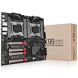
- Intel dual CPU sockets: This C612 server chip motherboard is designed with dual CPU sockets, which can support Intel Core i7 5th/6th generation processors and Xeon E5 V3/V4 series processors on LGA 2011-3 socket. (Note: If only one CPU is installed, please install it in the right slot, and the graphics card needs to be installed in the bottom two slots.)
- DDR4 4-channel memory slot: The memory slot of the LGA 2011-3 motherboard is designed with four channels, which can install 8 memory. It supports effective frequencies of 2133/2400MHz, and the maximum capacity is 256GB. (Non-ECC memory is not compatible when using E5 V4 series processors)
- PCIe 3.0 protocol standard: Equipped with 4 PCIe 3.0 X16 graphics card slots (with steel case). The transfer rate can reach 15.754 GB/s using one graphics card, and the performance can be improved by at least 50% by using two graphics cards. Equipped with dual M.2 hard disk slots, it can achieve fast reading even if multiple programs are running
- Stable power supply: use 24+8+8pin standard power supply interface (need to use a dedicated power supply for dual server motherboards), 12 (CPU) + 4 (memory) + 1 (C612 chip) phase power supply. Precise modularization provides good heat dissipation and makes the program run more stably
- Strong expandability: The X99 motherboard is equipped with multiple expansion interfaces to ensure that the motherboard has more room for improvement. These include 4*USB 3.0 ports, 4*USB 2.0 ports, 10*SATA 3.0 ports, 4*3pin sys fan, 2*4pin CPU fan. Besides, dual network ports allow your computer to do more things
- If only one program shows a jump, first suspect a sensor-map or interpretation issue and compare its log with a second independent source.
- If the value changes only at idle, consider power-state transitions, clock gating or telemetry behavior before concluding the rail is collapsing.
- If a field falls near zero, verify that it is a valid channel for the board; a power-gated domain or invalid sensor interpretation can produce a misleading value.
- If the value changes only under load, check the actual workload, Turbo state, load-line behavior, LLC and current limits.
- Use one monitoring utility consistently for the initial comparison and log readings rather than relying on a single screenshot.
Ordinary software polling can miss brief transients or distort their apparent timing. Software can identify a reporting inconsistency, but it cannot conclusively prove a dangerous voltage transient at the CPU die. That requires a correctly identified measurement point and appropriate electrical measurement.
Independent reader supportYour contribution helps us test, update, and keep practical guides available for everyone.Reproduce the behavior before changing BIOS settings
Record the starting configuration
- Record the exact motherboard model, CPU, BIOS version, memory kit and rated XMP speed. If you are troubleshooting an X99-S with an i7-6850K, verify CPU support against the ASUS list; ASUS lists BIOS 3004 as the minimum for that CPU.
- Photograph or write down all current BIOS voltage settings and save a BIOS profile if the board supports it.
- Return monitoring utilities to their default polling configuration. Close Intel XTU and vendor tuning applications so they do not apply software-side settings.
- Choose one monitoring application and log the values it exposes. Record VID, reported Vcore, CPU input voltage, VCCSA, VCCIO and cache/ring readings only where the board provides identifiable sensors.
Establish a baseline and isolate variables
- Load BIOS defaults and use JEDEC memory settings with XMP disabled. Record frequency and voltage readings at idle, during a short repeatable single-thread load and during an all-core load. Include package power and temperature where available.
- Repeat the same measurements after a cold boot and a warm reboot. Keep workload, monitoring tool and polling settings consistent.
- Enable XMP without changing CPU ratios or voltage settings, then repeat the measurements. If the change appears here, focus on memory-related support rails and firmware automation.
- Test C-States and EIST enabled versus disabled as a diagnostic comparison, changing only one setting at a time. Disabling power-saving features is not automatically a suitable permanent fix.
- If needed, test manual/override versus adaptive or offset control while keeping memory and CPU ratios unchanged. Use a conservative, validated setting; do not copy a universal voltage value from another system.
- Only after those comparisons, investigate LLC or a different stable BIOS revision. Record exact BIOS versions; available evidence does not establish a universal BIOS revision that fixes the reported behavior.
Decide whether the change is real
A stronger case for a real rail change requires repeatable readings from the same identified sensor at the same frequency, load and power-state conditions. Seek agreement from two independent telemetry sources or, preferably, an appropriate board-level measurement point. If the sensor identity is unknown or only one program reports the change, the result establishes a software display, not the voltage actually delivered.
Choose a configuration only after diagnosis
Manual or override mode
A manual/override setting can make a diagnostic baseline easier to interpret by reducing ambiguity from adaptive requests. It may also raise idle power and temperature or reduce power-saving behavior, so it is not automatically the best daily configuration. Use it to isolate behavior, not as a reason to apply a higher voltage.
Best Value

- LGA 2011-v3 Socket: The X99 Server motherboard support Intel LGA2011-v3 socket CPU processors (e.g. Intel Core i7 6950X/6900K/6850K/6800K/5960X/5930K/5820K, Xeon E5 1620/1680/2695/2696/2666/2686 V3; Xeon E5 2637/2690/2697/2683/4650 V4, etc.)
- Dual-channel DDR4: The Intel LGA 2011-3 gaming motherboard supports DDR4 Desktop/ECC/RECC memory up to 128GB (4*32GB), and supports 2133MHz/2400MHz
- Stable Power Supply: 8-phase power supply, all-solid-state capacitor design, fine workmanship, professional stability. And the DDR4 motherboard is equipped with 24+8 pin power interface (please use a brand power supply of at least 500w)
- Rich Interfaces: The Micro ATX placa madre features RJ45 gigabit network interfaces, and the maximum network transmission rate can reach 1000bps/s. And with M.2 slots (support NVME SSD/NGFF SSD), PCIe 3.0 X16, PCIe 2.0 x4, PCIe 2.0 x1, SATA 3.0, USB 3.0, USB 2.0
- Excellent performance: The DDR4 computer motherboard uses Intel C612 chipset and 8-layer PCB material. And with Heat dissipation armor protection for strong heat dissipation, to ensure stable bus communication
Adaptive or offset mode
Adaptive or offset operation preserves dynamic voltage and frequency behavior and can reduce idle power and temperature. Its readings vary with operating point, and a negative offset can destabilize idle, light-load or sleep/wake transitions even if an all-core stress test passes. Validate Turbo and demanding workloads as well as ordinary desktop use before relying on an offset.
LLC
Change LLC only when the observed issue is consistent with load-line behavior. Keep the board default or a moderate setting during diagnosis; aggressive LLC can change the relationship between requested and measured voltage and obscures the original question.
Quick Recap
When to return to defaults or seek board service
- Stop overclocking and return to defaults if a correctly identified rail exceeds your validated operating target.
- Investigate firmware and memory settings if the board repeatedly applies unexplained high VCCSA, VCCIO or input voltage, especially after XMP is enabled. First return to JEDEC memory settings and test memory stability independently.
- Do not keep stress-testing through WHEA errors, spontaneous resets, data corruption or uncontrolled temperature rise; these symptoms call for a stable stock configuration and further hardware diagnosis.
- Consider a board fault or service issue if a correctly identified rail remains unstable under controlled, repeatable conditions after the configuration and telemetry have been verified.
Product prices and availability are accurate as of the date/time indicated and are subject to change. Any price and availability information displayed on Amazon at the time of purchase will apply.

