
What’s actually slowing this PC down?
Pick the symptom - the matching free tool is one click away.
The INA128 is a suitable precision first stage for an experimental surface electromyography (sEMG) sensor, but it is not a complete muscle-sensing system. A practical design also needs electrodes, bias-current return paths, protection, filtering, a defined reference voltage, additional gain or digital processing, and a battery-powered or isolated connection to the recorder.
This design is appropriate for learning and non-diagnostic muscle-activation detection. It must not be used for diagnosis, patient monitoring, stimulation, or any body-connected setup tied directly to mains-powered equipment.
What an INA128 muscle sensor actually measures
Surface EMG detects the small bipolar voltage difference produced by muscle activity at the skin. Use two measuring electrodes over the target muscle and a third reference electrode, usually on a nearby relatively electrically quiet or bony area. The measuring electrodes are connected differentially to the INA128; the reference also provides a controlled return path for input bias currents.
Place the active electrodes along the muscle-fiber direction with consistent spacing. Clean and dry the skin, avoid wounds and highly mobile skin, secure the leads against pulling, and record the placement if comparing trials. Electrode position changes amplitude, frequency content, cross-talk and repeatability; the CEDE consensus treats electrode choice and placement as experimental-design decisions (CEDE electrode-selection consensus; surface-EMG detection best practices).
Free tools Windows power users keep installed
One-click scans. No signup required.
#1 Best Overall

- Muscle Electrical Sensor Module Muscle Analog Signal EMG Raw Signal Collection Electronic Development Kit for
EMG amplitude is an activation indicator, not a direct force measurement. Force relationships depend on muscle, contraction type, electrode position, tissue, fatigue and calibration. Intramuscular needle or fine-wire EMG is a different technique and is outside this project.
INA128 function, pins and specifications
The INA128 is a three-op-amp instrumentation amplifier. Its transfer function is:
VOUT = G × (VIN+ − VIN−) + VREF
For the INA128:
G = 1 + 50,000 / RG
RG is the resistor between pins 1 and 8. The output is shifted by the voltage on REF; it is not automatically referenced to ground.
| Pin | Function |
|---|---|
| 1 | Gain-resistor terminal |
| 2 | VIN− |
| 3 | VIN+ |
| 4 | Negative supply |
| 5 | REF |
| 6 | Output |
| 7 | Positive supply |
| 8 | Gain-resistor terminal |
TI specifies a gain range of 1 to 10,000 V/V, minimum CMRR of 120 dB, typical input noise of 8 nV/√Hz at 1 kHz, typical quiescent current of 700 µA, maximum input offset voltage of 50 µV, and a total operating-supply range of 4.5 to 36 V. Typical bandwidth is 1.3 MHz at gain 1 and 200 kHz at gain 100. Check the current INA12x datasheet, Rev. G (January 2026) and INA128 product page for limits, package details and output/input headroom.
Rank #2

- Muscle Electrical Sensor Module Muscle Analog Signal EMG Raw Signal Collection Electronic Development Kit for
High CMRR does not eliminate interference: it is finite and frequency-dependent, and impedance mismatch, a weak REF source, electrode imbalance and poor layout convert common-mode signals into differential error.
Use a complete signal chain, not just the amplifier
A robust one-channel design follows this order:
Surface electrodes
  → symmetrical protection and bias-current returns
  → INA128 differential preamplifier
  → high-pass/DC-offset removal
  → additional gain
  → low-pass anti-alias filter
  → ADC or precision rectifier
  → envelope/RMS processing and threshold
For raw recording, feed the band-limited, mid-supply-biased signal to an ADC. For a flex/no-flex controller, rectify or calculate RMS and smooth the result before applying a threshold.
Electrode inputs, protection and bias returns
Each INA128 input needs a DC path for its bias current. Add matched, high-value bias-return resistors from VIN+ and VIN− to the chosen analog reference. Without these paths, capacitive coupling or “open” electrodes can let the input common-mode voltage drift until the output saturates. Higher resistance loads the electrodes less but increases susceptibility to leakage, noise and slow recovery; choose values with the electrode impedance and filter network in mind. TI explains the design issue in Importance of Input Bias Current Return Paths in Instrumentation Amplifier Applications.
Use series resistors in both electrode leads and low-leakage, low-capacitance ESD protection where required. Keep protection symmetrical. Mismatched capacitance or resistance directly harms common-mode rejection. The INA128’s specified input protection (up to ±40 V under stated conditions) protects the component; it is not a patient-safety rating and does not permit arbitrary external voltages (TI product information).
Do these 3 things before closing this tab:
1Fix the driver behind crashes, sound loss and screen glitches2Clear out junk files and repair common Windows errors3Scan for outdated or missing drivers - takes under a minuteRank #3
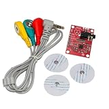
- AD8232 Module AD8232 Measurement Monitoring Sensor Module Kit Diy
Choose the power and reference arrangement
Dual supply
With isolated ±5 V or ±9 V rails, connect V+ and V− to the rails and drive REF from a low-impedance analog ground. Bipolar EMG can then be centered near 0 V. The supply must still be genuinely isolated and battery-powered when electrodes contact a person.
Single supply
For a 5 V system, generate a quiet reference near 2.5 V and buffer it with a suitable op amp. Connect INA128 REF to this low-impedance node and bias every following filter stage to the same voltage. A divider by itself is not a precision REF source: its impedance lets interference and output current disturb the reference and degrade CMRR. Verify the INA128 input common-mode range and output swing at the selected gain; do not assume a 3.3 V supply is sufficient, because TI specifies a 4.5 V minimum total supply.
Place local supply bypass capacitors close to the INA128 pins (a typical starting point is 100 nF ceramic at each supply connection plus appropriate bulk capacitance). Keep the reference quiet and separate from digital return currents.
Set gain in stages
Calculate the gain resistor with:
RG = 50,000 / (G − 1)
| Target gain | Calculated RG | Practical value |
|---|---|---|
| 10 | 5.556 kΩ | 5.62 kΩ |
| 20 | 2.632 kΩ | 2.61 kΩ |
| 50 | 1.020 kΩ | 1.02 kΩ |
| 100 | 505.1 Ω | 499 Ω or 511 Ω |
| 200 | 251.3 Ω | 249 Ω |
| 500 | 100.2 Ω | 100 Ω |
For example, gain 50 uses approximately 1.020 kΩ and produces VOUT = 50(VIN+ − VIN−) + VREF. Start the INA128 around 10–50 V/V, then add roughly 5–20 V/V in a later stage if needed. Total gain of 50–500 V/V is a reasonable experimental range, but it depends on electrode offset and the ADC range. A single 1,000× stage often saturates on electrode DC offsets or movement before filtering can remove them.
Rank #4

- Muscle Electrical Sensor Module Muscle Analog Signal EMG Raw Signal Collection Electronic Development Kit for Arduino
Filter the signal for the application
Raw sEMG is not confined to one universal band. A common starting design uses a 10–20 Hz high-pass and a 400–500 Hz low-pass for broader recording. A simple activation detector may use a 100–200 Hz low-pass. A published filtering study recommends a 20 Hz high-pass with a 12 dB/octave slope when movement artifact is important (filtering study). Educational material often describes useful content near 20–200 Hz, but the spectrum depends on muscle, electrodes, placement and instrumentation (University of Oklahoma EMG tutorial).
High-pass stage
Use it to remove electrode DC offset, baseline drift and much low-frequency motion artifact. A lower corner preserves more information; a higher corner improves movement rejection but can alter slow components.
Low-pass and anti-alias stage
Use it to limit noise and prevent out-of-band energy from folding into the ADC. If retaining 400–500 Hz, sample at least twice that frequency; 1 kS/s or faster is a practical starting point. The filter’s order, Q, gain, phase, component tolerance and op-amp headroom all matter.
Notch filtering
A 50 or 60 Hz notch may help after physical causes are corrected, with 60 Hz common in the United States and 50 Hz in many other regions. First improve battery operation, electrode contact, twisted short leads, impedance symmetry, reference routing and PCB layout. A notch can remove real signal components and cannot repair a ground loop.
The Tool Desk
Outbyte PC Repair FREERepair Windows errors before they cause bigger problemsFix Now →Outbyte Driver Updater FREEScan for outdated or missing drivers - takes under a minuteDriver Scan →Best Value

- By detecting the electromyogram (EMG), measuring muscle activity has traditionally been used in medical research.
- With the advent of shrinking but more powerful microcontrollers and integrated circuits EMG power, the sensors can be used for various control systems.
- Sensor will measure filtering, rectifying electrical activity of the muscle output 0-Vs volts, the output size to take, depending on the amount of muscle activity is selected.
- Easy to use controller to detect muscle activity
- Compact, designed for Microcontrollers, Send data, Breadboard compatible.
Passive RC filters are simple but have limited roll-off and can load stages. Active Sallen–Key and multiple-feedback filters provide sharper responses but require correct component values and a stable op amp. Digital filtering remains flexible only after adequate analog anti-alias filtering.
Turn bipolar EMG into an activation signal
Raw EMG is bipolar. A usable activation level requires processing:
- Band-limit the amplifier output.
- Full-wave rectify it, or rectify samples in software.
- Low-pass the rectified signal to form a linear envelope, or calculate RMS/mean absolute value over a moving window.
- Set a calibrated threshold, preferably with hysteresis and a minimum activation duration.
A precision rectifier avoids the signal loss of an ordinary diode at low amplitudes. For beginners, ADC sampling followed by digital rectification, moving-average smoothing or RMS calculation is usually easier to calibrate. Raw waveform, rectified waveform, linear envelope and RMS are different outputs and should not be treated as interchangeable.
Independent reader supportYour contribution helps us test, update, and keep practical guides available for everyone.Build and test safely
Follow this sequence before attaching electrodes:
- Inspect polarity, pinout, solder joints, protection and decoupling with the circuit unconnected to a person.
- Verify supply rails and measure the buffered REF voltage.
- Apply a known small differential test voltage and confirm the calculated INA128 gain at low gain.
- Check each filter stage’s expected corner and output range.
- Run the complete body-connected circuit from batteries. Do not connect a subject while it is tied to a bench supply, USB oscilloscope, desktop computer or other potentially earth-referenced equipment unless the entire system is properly isolated.
- Connect electrodes only after the isolated circuit passes electrical checks.
- Begin with a large, superficial muscle such as the biceps. Measure resting noise, then active amplitude, and set thresholds from those measurements.
A blocking capacitor alone is not medical isolation. Safe body-connected equipment may require galvanic isolation, current limiting, leakage-current analysis, creepage and clearance, protective measures and compliance with applicable standards. Instrumentation standards cover electrodes, amplifiers, filters, artifacts, sampling and external communication (IFCN EMG instrumentation standards; Delsys sEMG tutorial). Stop immediately for discomfort, skin irritation, heating or an electrical sensation. Never combine this circuit with electrical muscle stimulation.
Layout and construction choices
- Prefer a PCB or compact soldered prototype over a solderless breadboard; breadboards add parasitic capacitance, leakage, long unshielded paths and unstable references.
- Keep VIN traces short, symmetrical and away from clocks and switching regulators.
- Use twisted differential electrode wires, strain relief and small cable loops.
- Route the reference deliberately; shielding helps only when connected without creating ground-current paths.
- Keep digital and analog return currents from sharing the sensitive electrode path.
Troubleshoot by symptom
| Symptom | Likely causes | Recovery |
|---|---|---|
| Output stuck at a rail | Excessive gain, electrode offset, missing bias return, wrong supply/pinout, REF error or common-mode violation | Set gain near 10, test with a known differential signal, verify rails and REF, confirm both DC return paths, then reconnect electrodes |
| Large 50/60 Hz waveform | Mains coupling, poor contact, long leads, floating reference, impedance imbalance or computer ground loop | Use batteries, remove USB, shorten/twist leads, prepare skin, check reference and matched impedances; add a notch only afterward |
| Signal changes when cable moves | Motion artifact, triboelectric cable noise or electrode tugging | Secure cable and electrodes, add strain relief, replace poor electrodes, reposition, or raise the high-pass corner if acceptable |
| LED flickers unreliably | Thresholding raw bipolar EMG, no envelope, threshold near noise floor, no calibration or saturation | Rectify or calculate RMS, smooth, measure rest noise, add hysteresis/minimum duration and recalibrate |
| No visible muscle signal | Wrong placement or pinout, poor contact, wrong test node, unsafe scope connection, gain too low or filtering out the signal | Test with a known input, check supplies and REF, inspect each stage, try a large superficial muscle and increase gain gradually |
When another solution is better
| Requirement | Practical direction |
|---|---|
| Learning a discrete analog front end | INA128 |
| Low-voltage battery wearable | Modern low-voltage instrumentation amplifier or integrated biopotential AFE |
| Several EMG channels | Dedicated multichannel EMG/biopotential front end |
| Wireless sensor | AFE with an isolated or wireless data path |
| Fast robot/LED trigger | Commercial EMG module or conservative INA128 front end |
| Diagnosis or patient care | Certified clinical EMG equipment |
TI presents the INA828 as a newer related instrumentation amplifier with lower noise and input bias current, and the INA333 as a low-power, low-voltage option. They are candidates, not automatic pin-compatible replacements; compare supply range, headroom, bandwidth, bias current, CMRR, ADC needs and safety architecture. TI’s INAEVM can help evaluate instrumentation-amplifier behavior, but it is not a human-safe EMG system by itself.
Buy an INA128 when the goal is learning the analog design, use the evaluation module to prototype amplifier behavior, choose a complete module for a quick controller project, and use certified clinical equipment for medical work. Component protection and a good waveform never establish medical suitability.
Quick Recap
Sources and design references
- TI INA128 product page
- TI INA12x datasheet, Rev. G, January 2026
- Merletti and Cerone: surface EMG best practices
- CEDE project
Product prices and availability are accurate as of the date/time indicated and are subject to change. Any price and availability information displayed on Amazon at the time of purchase will apply.

