
A spring-return push or push-pull solenoid can press an existing physical button. Choose it by the button’s measured force and travel—not voltage alone—and mount it with an adjustable tip and a hard stop so the plunger cannot overtravel the switch. If a microcontroller controls the coil, use an external power supply, a transistor or MOSFET driver, and a flyback diode.
What you need
- A DC push or push-pull solenoid with suitable force, stroke, return action, and duty cycle.
- A power supply matched to the solenoid’s rated voltage and operating current.
- A rigid mounting bracket, adjustable contact tip, and compliant pad such as rubber or silicone.
- A physical stop to limit button travel.
- For electronic control, a suitably rated transistor or logic-level MOSFET, a flyback diode, and control wiring.
- Optionally, a controller, a lockout timer, and a sensor to confirm that the button changed state.
Push, pull, and push-pull solenoids
A push solenoid extends its rod when energized; a pull solenoid retracts its rod. The names describe rod movement, so check the exact model and intended mounting direction before ordering. A push-pull model can push from one end and pull from the other, depending on its construction and how it is mounted. See McMaster’s push-solenoid listings and electric-solenoid categories for the terminology.
For a typical momentary button, start with a spring-return DC push or push-pull solenoid. Its spring or the button’s own return spring should release the button when power is removed. Do not assume every model has a return spring or captive plunger; confirm those details in its specifications. For example, Adafruit’s small product 412 is described as having a captive armature and return spring.
Measure the button before choosing an actuator
Measure both how far the button must move and how much force it takes to actuate it. A solenoid’s force changes with plunger position, so a starting-force figure does not mean it supplies that force throughout its stroke. Force at a particular stroke, starting force, and holding or retentive force are different specifications.
Free tools Windows power users keep installed
One-click scans. No signup required.
#1 Best Overall

- Product Specifications: 12V Micro DC Solenoid Electromagnet made of metal and electric magnets electronic parts; Note: The product wire color is random, does not distinguish between positive and negative poles
- Electrical Characteristics: Rated Voltage DC 12V with approximately 5.5W power consumption; Push Pull Type with load current 460mA; Coil Resistance approximately 26ohm; Initial Thrust (pull) ranges from 0.15N to 0.2N
- Important Usage Warning: Due to its small size and large working current, this solenoid generates significant heat and is not suitable for long-term power-on operation. It is recommended that the power-on time does not exceed 1 minute and is suitable for instant power-on use only
- Precise Dimensions: Stroke of 4mm/0.157inch; Body Size 1.02x0.39x0.31inch (Including prominent parts); Head Shaft Length 0.35inch (thick head length 0.137inch); Head shaft diameter 0.196inch (Head hole diameter 0.07inch); Tail shaft diameter 0.12inch; Cable Length 230mm/9.0inch (No distinction +/-); Body fixed hole diameter M2 x4
- Package Contents and Weight: Includes 4 Push Pull Type DC Solenoid Electromagnets; Each piece weighs 0.26oz providing lightweight construction for various applications
- Measure the distance from the button’s released position to the point at which it has fully actuated. If practical, also note the travel to the electrical switching point.
- Use a spring scale or force gauge to measure force near the switching point and near the end of travel. Include any cover, membrane, friction, or linkage load.
- Choose an actuator with margin. A common starting point is at least twice the measured button force; allow more if alignment is imperfect, the mount flexes, or long-term reliability matters.
- Compare force at the relevant stroke—not just the solenoid’s strongest or starting-force figure—with the required force.
Solenoid force, speed, and travel trade off against one another. A lever can increase force at the button, but it also changes the required actuator travel and may slow the motion. Better alignment and lower friction can be more effective than simply choosing the largest solenoid.
Choose stroke, voltage, current, and duty cycle
Stroke and overtravel
The solenoid needs enough travel to actuate the button, but extra travel must not be allowed to crush or damage it. If a button moves 3 mm, for example, a 5–10 mm solenoid stroke may be usable when an adjustable tip or mechanical stop limits the button’s actual movement. The bracket—not the solenoid’s internal stop—should set the button’s maximum travel.
Rank #2
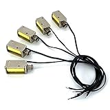
- Product Name : 12V Micro DC Solenoid Electromagnet; Material : Metal, Electric Magnets Parts ;
- Rated Voltage : DC 12V; Power: approx.2.5W; Push Pull Type; Load current 210mA (generally 200mA after heating); Coil Resistance: approx. 55ohm
- Stroke : 4mm/0.157inch; Body Size : 1.15x0.39x0.43inch (Including prominent parts);Head shaft diameter: 0.157inch (with gasket diameter 0.26inch); Tail shaft diameter: 0.12inch;
- Cable Length : 9.0inch (No distinction +/-); Color : As Picture Shown
- Weight : 0.38oz / Per; Package Content : 5 x Push Pull Type DC Solenoid Electromagnet
Voltage and current
Match the supply voltage to the solenoid’s rating, and ensure the supply and driver can provide its operating current without excessive voltage drop. For a resistive DC coil, estimates are I ≈ V/R and P ≈ V × I; use the manufacturer’s stated current where available and verify any conflicting figures before committing to a driver or supply.
Published examples illustrate why specifications need context. Adafruit’s small 12-VDC product 412 is listed at approximately 300 mA, with a 5.5 mm throw, 0.5 N starting force, and 5 N retentive force. Those two force figures describe different operating conditions. Its larger 12-VDC product 413 is listed with a 10 mm throw and 6 N starting force at 12 VDC and 50% duty cycle. However, that product page gives current-related figures that do not reconcile cleanly: it mentions an approximately 250 mA surge and lists approximately 12 ohms coil resistance, which implies about 1 A at 12 V by the simple resistance calculation. Verify the datasheet or measure the actual coil current before sizing the supply and driver.
Do these 3 things before closing this tab:
1Clear out junk files and repair common Windows errors2Fix the driver behind crashes, sound loss and screen glitches3Repair Windows errors before they cause bigger problemsRank #3

- 【Product Specifications】: Model name:1039B; Maximum push-pull force: 1.5-20N; Stroke: 12mm; Voltage: DC12V; Current: 1.2A;Thread hole size: M4;Installation hole size:Ø3
- 【Working Principle】: When powered on, the push-pull rod pushes out and generates magnetism, and when powered off, the power and magnetism of the push-pull rod disappear
- 【Usage】: The wiring method does not distinguish between positive and negative poles. Within the rated voltage range, the push force can be adjusted by adjusting the voltage
- 【Attention】: The power on time should not be too long (less than 30 seconds). Switching power supplies, transformers, high-power lithium batteries should be selected instead of dry batteries, power banks, etc
- 【Application Scenarios】: Push pull type solenoid electromagnet valves are suitable for various types of industrial automation control equipment, such as switch control, locking mechanisms, household appliance control, and other applications that require frequent actions
Do not power a solenoid directly from a microcontroller GPIO, a development board’s regulator, an undersized adapter, or a small rectangular 9-V battery. Adafruit specifically says its product 413 needs a separate supply and should not be powered from a 9-V battery. Check the product specifications for that model rather than generalizing the warning to every battery or solenoid.
Duty cycle
A solenoid that is safe for a short pulse may overheat if held on. Use continuous operation only when the exact model is rated for continuous duty and its thermal conditions are suitable. McMaster’s listings include intermittent-duty examples with limits such as 1 minute on/9 minutes off, 2.5 minutes on/22.5 minutes off, 3 minutes on/27 minutes off, and, for certain sealed models, 1 minute on/3 minutes off. These are examples for particular products, not universal limits. Check the selected model’s rating at McMaster’s push-solenoid listings or its manufacturer documentation.
Rank #4

- 【Product Specifications】: Model name: 1564B; Maximum push-pull force: 3.5-35N; Stroke: 20mm; Voltage: DC12V; Current: 2A;Thread hole size: M3;Installation hole size:Ø5
- 【Working Principle】: When powered on, the push-pull rod pushes out and generates magnetism, and when powered off, the power and magnetism of the push-pull rod disappear
- 【Usage】: The wiring method does not distinguish between positive and negative poles. Within the rated voltage range, the push force can be adjusted by adjusting the voltage
- 【Attention】: The power on time should not be too long (less than 30 seconds). Switching power supplies, transformers, high-power lithium batteries should be selected instead of dry batteries, power banks, etc
- 【Application Scenarios】: Solenoid electromagnet valves are suitable for various types of industrial automation control equipment, such as switch control, locking mechanisms, household appliance control, and other applications that require frequent actions
Mount the solenoid so it presses squarely
A well-aligned mount is central to reliable operation. Attach a rigid bracket to the same structure that holds the button, and keep the plunger axis parallel to the button’s movement. Side-loading can bind the plunger; a flexible or adhesive-only prototype mount can drift with vibration, repeated impacts, or temperature changes.
- Use slotted holes to make alignment adjustable, then secure the bracket firmly.
- Add a threaded tip or adjustment screw for fine positioning and a small air gap when released.
- Place a compliant rubber or silicone pad at the contact point to absorb minor alignment errors and soften impact.
- Fit a hard stop so the mechanism cannot push the button beyond its safe travel.
- Keep the tip centered on the button and avoid loading its edges or a fragile cover.
- Leave clearance for the plunger, wiring, heat dissipation, and any return movement; make the mount removable if the original device must remain unmodified.
Wire a microcontroller-controlled solenoid
Use a low-side switch: the controller’s GPIO drives a transistor or logic-level N-channel MOSFET, while a separate supply powers the coil. The GPIO is a control signal, not a source for the solenoid’s current. Adafruit likewise specifies a power transistor and diode for microcontroller control of its solenoid; its RP2040 example uses a GPIO output with a driver circuit.
Best Value

- 【Product Specifications】: Model name: 0837B; Maximum push-pull force: 1-10N; Stroke: 10mm; Voltage: DC12V; Current: 1A; Thread hole size: M3;Installation hole size:Ø3
- 【Working Principle】: When powered on, the push-pull rod pushes out and generates magnetism, and when powered off, the power and magnetism of the push-pull rod disappear
- 【Usage】: The wiring method does not distinguish between positive and negative poles. Within the rated voltage range, the push force can be adjusted by adjusting the voltage
- 【Attention】: The power on time should not be too long (less than 30 seconds). Switching power supplies, transformers, high-power lithium batteries should be selected instead of dry batteries, power banks, etc
- 【Application Scenarios】: Linear solenoid valves are suitable for various types of industrial automation control equipment, such as switch control, locking mechanisms, household appliance control, and other applications that require frequent actions
External +12 V ───── Solenoid coil ───── MOSFET drain
                                           MOSFET source ───── External supply GND
Microcontroller GPIO ── gate resistor ─── MOSFET gate
Microcontroller GND ───────────────────── External supply GND

Flyback diode across the coil:
Cathode (striped end) ─────────────────── +12 V
Anode ────────────────────────────────── MOSFET drain / coil low side
The diagram shows a 12 V example; use the selected solenoid’s rated supply voltage. Choose a logic-level MOSFET whose on-resistance is specified at the controller’s actual gate voltage and whose current and voltage ratings suit the coil. A gate resistor of about 100–330 ohms and a gate pull-down of about 10 kΩ are typical starting values. Size the diode for at least the coil current and suitable reverse voltage.
Connect the flyback diode’s cathode to the positive supply and its anode to the switched low side. Reversing it can effectively short the supply when the solenoid turns on. Use a separate fuse or current protection where appropriate. If long supply wiring or coil activation causes controller resets, add bulk capacitance near the driver, reduce wiring resistance, and check the supply voltage under load. Tie the controller and external supply grounds together for this non-isolated low-side arrangement.
Independent reader supportYour contribution helps us test, update, and keep practical guides available for everyone.Set a press-and-release sequence
For a momentary press, energize the coil long enough to complete the button travel, then turn it off and allow the mechanism to return before accepting another command. Start testing with a conservative 100–500 ms press interval and 100–500 ms release interval; these are starting ranges, not universal settings. Tune them for the solenoid, button, supply, and mounting, while keeping within the solenoid’s duty-cycle limits.
when trigger received:
    if actuator is not busy:
        mark actuator busy
        turn solenoid on
        wait for press interval
        turn solenoid off
        wait for release interval
        mark actuator ready
A sensor can confirm the target button changed state or that the plunger returned before another press. Depending on the installation, options include a microswitch, optical interrupter, Hall sensor with a magnet, a safe signal from the controlled equipment, or a camera. Do not connect to an equipment signal unless its voltage and isolation are understood.
Troubleshoot common failures
The solenoid clicks but does not press the button
- Possible causes: Too little stroke or force at the required position, a flexing bracket, off-center contact, misalignment, or supply voltage sag under load.
- Checks and fixes: Measure button travel and force; test the solenoid from a correctly rated supply; measure supply voltage while energized; stiffen the mount, center and adjust the tip, or use a lever or better-matched actuator.
The button presses but does not release
- Possible causes: No solenoid return spring, weak button return, a tip wedged against the button, excessive on-time, or a side-loaded plunger.
- Checks and fixes: Confirm the model’s return behavior; add clearance at rest, shorten the press interval, and correct alignment. Add a separate return spring only if it will not overload the button.
The microcontroller resets during activation
- Possible causes: The coil shares an inadequate controller supply, high-current wiring causes voltage drop, the supply is undersized, or coil suppression or grounding is wrong.
- Checks and fixes: Use a separate coil supply, verify diode polarity and common-ground connections, measure voltage during activation, and use shorter or heavier coil wiring. Bulk capacitance near the driver may help with wiring-related dips.
The MOSFET overheats
- Possible causes: A MOSFET that is not fully enhanced at the GPIO voltage, insufficient current or voltage rating, a floating gate, or coil current higher than expected.
- Checks and fixes: Check on-resistance at the actual gate voltage, add a gate pull-down, measure coil current, and select a suitably rated device. Provide heat sinking if the design requires it.
The solenoid overheats
- Possible causes: Exceeding an intermittent-duty rating, excessive press time or trigger frequency, overvoltage, or mechanical binding.
- Checks and fixes: Enforce a maximum on-time and lockout in software, keep the coil at rated voltage, remove binding, or choose a continuous-duty model if the application requires sustained energization.
The button is damaged or presses inconsistently
- Possible causes: Excessive force or travel, hard impact, no mechanical stop, shifting mount, edge contact, or operation beyond the button’s mechanical life rating.
- Checks and fixes: Add a compliant tip and firm stop, adjust the mount, reduce force with a suitable linkage, or use a servo for controlled motion. Check the button’s actuation and life specifications.
When another actuator is a better fit
| Option | Best fit | Trade-off |
|---|---|---|
| Push or push-pull solenoid | Short, fast momentary movement; fixed alignment; modest force; press frequency within the model’s duty cycle. | Often makes an impact, offers little positional control, and may need cooling between presses. |
| Servo | Controlled press and release, adjustable travel or pressure, position feedback, or gradual motion. | More complex motion and control than a simple pulse actuator. |
| Geared motor and cam | Repeated presses at predictable intervals, mechanical advantage, or holding position without continuous coil power. | Slower and mechanically more involved. |
| Commercial linear actuator | Substantial force or travel, durability, or limit switches and position feedback. | Typically larger, costlier, and noisier than a small button pusher. |
| Replace or electrically parallel the button | You control the equipment, modification is safe and permitted, and electrical actuation is preferable to a mechanical press. | Requires understanding the circuit, voltage, isolation, safety implications, and any warranty restrictions. |
For industrial panel controls, a replacement assembly may be an option where modification is permitted. McMaster’s push-button panel actuators include modular actuators and contact blocks, with different sizes, reset styles, and IP/NEMA options. An IP rating on a component does not make the complete assembly waterproof; enclosure, cable entry, and installation matter too.
Quick Recap
Safety before installation
- Hazardous equipment: Treat buttons controlling mains-powered, heated, moving, medical, security, or emergency equipment as safety-relevant. A mechanical pusher avoids some circuit modifications, but it does not make an unsafe or unsuitable control system safe. Do not bypass emergency stops or protective interlocks.
- Electrical modification: Do not wire in parallel with a safety-critical or mains-connected button unless the circuit, isolation, and applicable requirements are understood. Use qualified help where needed.
- Heat and fire: Keep the coil within its voltage and duty-cycle ratings, protect wiring appropriately, and mount the assembly so heat can dissipate.
- Pinch and impact: Guard the plunger and linkage where fingers or nearby parts could be caught. Use strain relief and an enclosure appropriate to the environment.
Product prices and availability are accurate as of the date/time indicated and are subject to change. Any price and availability information displayed on Amazon at the time of purchase will apply.

