
Quick wins for a faster PC:
Scan for outdated or missing drivers - takes under a minuteDriver Scan →Repair Windows errors before they cause bigger problemsFix Now →Fix the driver behind crashes, sound loss and screen glitchesFind Drivers →For a microcontroller-generated PWM signal, start with a 10 kΩ linear potentiometer wired as a voltage divider. Connect its outer terminals to the ADC reference voltage and ground, and connect the wiper to an analog input. For a 555 PWM circuit, choose a linear potentiometer from the timing-resistance calculation instead—often 10 kΩ to 100 kΩ. Do not put a small potentiometer in series with a motor, lamp, or heater; use it to command a transistor, MOSFET, driver, or controller.
First identify where the potentiometer is used
“PWM control” can describe different circuits, and the correct potentiometer depends on the topology.
| Application | What the potentiometer does | Normal starting choice |
|---|---|---|
| Arduino or other microcontroller | Provides an analog command voltage to an ADC | 10 kΩ, linear, single-turn |
| 555 timer | Sets timing resistance, affecting oscillator frequency and duty cycle | Linear pot selected with the timing capacitor and fixed resistors |
| Motor, lamp, heater, or other power load | Should normally set a controller command, not carry load current | Small-signal pot plus MOSFET, transistor, or driver stage |
A mechanical potentiometer does not normally generate PWM. The PWM waveform comes from a microcontroller timer, 555 timer, dedicated controller, or driver IC.
Best potentiometer for Arduino and MCU PWM
Use a 10 kΩ linear pot
A 10 kΩ linear potentiometer is a robust general-purpose default for a directly sampled analog input. It offers lower source impedance and better noise and ADC settling behavior than unnecessarily high values, while consuming little current. A 5 kΩ part can improve drive and noise performance; 20 kΩ is often acceptable; 50 kΩ or 100 kΩ may require longer acquisition time, filtering, buffering, or firmware averaging. A 1 MΩ pot is usually unsuitable for a directly sampled ADC unless the circuit is designed for it.
Free tools Windows power users keep installed
One-click scans. No signup required.
#1 Best Overall

- Product name:Potentiometer Kit;Model:WH148 B1K 5K 10K 20K 50K 100K 250K 500K 1M ohm ;Type:Rotary Potentiometer Single Linear (B Type ).
- Product parameters:Shaft Length: 15 mm ;shaft diameter: 6 mm ;Overall dimensions of potentiometer:24mm x 17mm x 25mm (0.93in/0.66in/0.97in)(L*W*H).knob Size: 15 x 17 mm (d*h).
- Product material:potentiometer is made of metal and carbon film,The knob is made of plastic, easy to use and install.
- Widely used:It is suitable for volume control in audio applications, guitars, stereos, household equipment and personal audio equipment.
- Product packaging:10pcs B10K potentiometer + B1K 5K 20K 50K 100K 250K 500K 1M potentiometer (5 for each value)+30PCS White plastic knob +10PCS Black plastic knobs+10PCS blue plastic knobs+50PCS Washer+50PCS Nut.(In a plastic box)
With a 10 kΩ pot across 5 V, divider current is approximately 0.5 mA. With 100 kΩ, it is approximately 50 µA. Choose the lowest resistance that meets your power budget and the ADC’s source-impedance requirements rather than automatically choosing the highest value.
Choose linear taper
A linear taper changes resistance approximately in proportion to shaft rotation, making the software control range predictable. Audio or logarithmic taper is intended for perceived loudness and usually feels unintuitive for duty-cycle control. Taper letters such as A, B, and C are not standardized consistently across every manufacturer, so verify the datasheet. Manufacturer specifications also define model-specific power dissipation and wiper behavior; do not infer them from the resistance value alone (manufacturer potentiometer documentation).
Power rating for an ADC control
For a voltage-divider input, dissipation is small. At 5 V, a 10 kΩ pot dissipates P = V²/R = 2.5 mW; a 1 kΩ pot dissipates 25 mW. A normal small panel or PCB pot is therefore adequate if its voltage, environmental, and mechanical ratings suit the product.
Wire the potentiometer as a voltage divider
VREF ───── outer terminal
           |
        potentiometer
           |
GND  ───── outer terminal

wiper ───── analog-input pin
- Connect one outer terminal to the same reference voltage used by the ADC (5 V on a 5 V design or 3.3 V on a 3.3 V design).
- Connect the other outer terminal to controller ground.
- Connect the wiper to the analog input.
- Keep the wiper lead short and away from motor and MOSFET switching wiring.
- If the direction feels backward, swap the two outer terminals; leave the wiper connected to the ADC.
Do not power a divider from 5 V when the ADC input is not 5 V tolerant. A mismatched reference can overvoltage the input or make readings vary with supply voltage.
Rank #2

- Potentiometer assortment: Type:Rotary Potentiometer Single Linear (B Type );Model:WH148 B1K 2K 5K 10K 20K 50K 100K 250K 500K 1M ohm.
- Product material:potentiometer is made of metal and carbon film, very stable and durable,The knob is made of plastic,Durable, easy to use and install.
- Product parameters: shaft diameter: 6 mm ;Shaft Length: 15 mm ;3 Terminals;Overall dimensions of potentiometer:24mm x 17mm x 25mm (0.93in/0.66in/0.97in)(L*W*H).knob Size: 15 x 17 mm (d*h)
- Widely used: It is suitable for volume control in audio applications, guitars, stereos, household equipment and personal audio equipment
- Package Lists:WH148 -B1KΩ*2;WH148 -B2KΩ*2;WH148 -B5KΩ*2;WH148 -B10KΩ*2;WH148 -B20KΩ*2;WH148 -B50KΩ*2;WH148 -B100KΩ*2;WH148 -B250KΩ*2;WH148 -B500KΩ*2;WH148 -B1MKΩ*2;White plastic knob*20;Nut*20; Washer*20;High quality plastic box*1
Arduino mapping example
Arduino’s documented example reads a potentiometer with a default 10-bit value of 0–1023 and maps it to an 8-bit PWM command of 0–255 (Arduino PWM documentation).
const int potPin = A0;
const int pwmPin = 9;

void setup() {
  pinMode(pwmPin, OUTPUT);
}

void loop() {
  int potValue = analogRead(potPin);       // typically 0–1023
  int pwmValue = map(potValue, 0, 1023, 0, 255);
  analogWrite(pwmPin, pwmValue);
}
Check your board documentation before copying those ranges. ADC resolution, PWM resolution, PWM-capable pins (often marked with ~), analog-reference settings, and analogWrite() behavior vary between board families. Some cores support analogWriteResolution().
Limit unsafe endpoints
int pwmValue = map(potValue, 0, 1023, 20, 235);
pwmValue = constrain(pwmValue, 20, 235);
analogWrite(pwmPin, pwmValue);
Limiting the range can prevent a motor stall, an unsafe heater output, an LED-driver minimum-pulse problem, or a full-power command. Choose the limits from the load and driver requirements, not from the potentiometer.
Selecting a pot for a 555 PWM circuit
In a conventional 555 astable, the potentiometer is part of the timing network. Its value cannot be selected independently from frequency and capacitance. For the conventional topology:
Rank #3
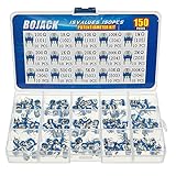
- BOJACK High Quality Variable Resistor 6mm Potentiometer Assortment Kit
- Rated power: 0.1W
- Max Operating Voltage: 50 V
- Potentiometer Model:15 Type-100Ω(101),1KΩ(102),10KΩ(103),100KΩ(104),1MΩ(105),200Ω(201),2KΩ(202),20KΩ(203),200KΩ(204),2MΩ(205),300KΩ(304),500Ω(501),5KΩ(502),50KΩ(503),500KΩ(504)
- Package Quantity: 150 pcs (Each model 10 pcs), Packed in A plastic storage case
f ≈ 1 / [0.693 (RA + 2RB) C]
Here, RA is a fixed resistor, RB is the timing resistance (which may include the pot), and C is the timing capacitor. A practical design sequence is:
- Set the required PWM frequency.
- Choose a practical timing capacitor.
- Calculate the required timing resistance.
- Select a linear potentiometer whose useful range covers that resistance.
- Add fixed resistors to prevent an unsafe near-zero value and define the endpoints.
Hobby circuits often use 100 kΩ, but that is not universal. Too-small values increase timing current and may narrow the adjustment range; too-large values increase sensitivity to leakage, noise, stray capacitance, and capacitor imperfections. A conventional 555 astable also does not independently vary duty cycle from nearly 0% to nearly 100% because charge and discharge paths overlap. Separate paths using diodes and resistors are commonly used for a wider duty-cycle range. TI’s TLC555 product page provides astable design resources; confirm operating limits in the applicable datasheet.
Why the pot should not carry motor current
A small signal potentiometer is not a motor-speed resistor. Direct series control wastes power as heat, reduces motor torque, stresses the wiper and track, and can damage the part. The usual architecture is:
potentiometer → ADC or control input → PWM output → gate/base driver → load
For a DC motor, use a suitable logic-level MOSFET or motor driver, gate resistor, supply decoupling, and a flyback path for the inductive load. Select the switching stage for voltage, current, gate-drive voltage, thermal dissipation, and the required PWM frequency.
Rank #4

- 1K 2K 5K 10K 20K 50K 100K 250K 500K 1M 80pcs potentiometer kit , Individual Compartment, 1k potentiometer 5k potentiometer 10k potentiometer 20k potentiometer 50k potentiometer 100k potentiometer
- 24 rotary knob or potentiometer knobs linear potentiometer, 20 linear potentiometers 20 washers 20 nuts
- Diverse assortment of potentiometers ranging from 1k to 1M potentiometer, making it an ideal choice for professionals and hobbyists working with electronic parts.
- Each potentiometer comes with a durable knob for easy adjustment. Rotary design allows for smooth operation, perfect for use in guitar pedals, audio devices, and arduino projects.
Use a power potentiometer directly only when the design intentionally dissipates power and the part’s total track rating, wiper-position rating, wiper current, terminal voltage, temperature derating, pulse behavior, and inductive-load suitability have all been checked.
Noise, jitter, and settling
Stationary readings can move because of wiper contact noise, long wires, PWM switching interference, poor grounding, ADC quantization, or insufficient acquisition time.
- Prefer 5 kΩ or 10 kΩ in noisy or fast-sampling ADC applications.
- Keep the wiper wire short and route it away from motor and MOSFET nodes.
- Start with 10 nF to 100 nF from wiper to ground.
- Average several ADC samples or apply software hysteresis/deadband.
- Use sound logic-ground and power-ground layout and local supply decoupling.
A larger capacitor or higher resistance makes the control slower, so verify that the knob still responds acceptably.
Independent reader supportYour contribution helps us test, update, and keep practical guides available for everyone.Mechanical versus digital potentiometers
A mechanical pot is usually best for a physical knob and continuous adjustment. A multi-turn part improves repeatability when a single-turn control is too sensitive; sealed or industrial versions suit dust, moisture, vibration, or frequent operation.
Recommended Free Tools
Best Value

- This mini PWM controller DC motor speed regulator 5V-16V 12V speed regulation with switch function 10A LED dimming speed regulation module
- Maximum voltage: 16V, Minimum voltage: 5V, Continuous current: 10A, Short-circuit limit current: 20A (less than 10 seconds)
- Speed control mode: PWM stepless speed regulation, can also be used to adjust the light
- Adjustable resistor switch: open the switch in clockwise direction, rotate the potentiometer clockwise to accelerate the motor; rotate the potentiometer counterclockwise to decelerate the motor
- Note: The module needs to be connected to the load, adjust the potentiometer output voltage will be changed
A digital pot is useful for firmware-controlled calibration, remote adjustment, or a product without a mechanical control, but it is not a universal replacement. Examples include the AD5245 (256 positions, 5 kΩ/10 kΩ/50 kΩ/100 kΩ options, 2.7–5.5 V), AD5115 (32 positions, 2.3–5.5 V, up to ±6 mA specified wiper current), and MAX5450–MAX5455 family (256 taps, 10 kΩ/50 kΩ/100 kΩ, 2.7–5.5 V). See the AD5245, AD5115, and MAX5455 product pages.
Before substituting one, check terminal-voltage range, wiper current, wiper resistance, end-to-end value, number of steps, interface, power-up state, and whether its internal switches can tolerate the signal. Analog Devices explains that allowable digital-pot current is constrained by terminal voltage, power dissipation, and switch capability (digital-pot current FAQ). Many devices power up at midscale, which can be unsafe if the load must start at zero; behavior is device-specific (Analog Devices application note). Do not connect a low-voltage digital pot to a 9 V or 12 V 555 timing node without verifying its limits.
Troubleshooting common failures
PWM remains at zero or full scale
- Verify the wiper is on the intended analog pin.
- Check both outer terminals, reference voltage, and common ground.
- Confirm the selected output pin supports PWM.
- Match software ADC and PWM ranges to the board.
- Test the pot for the expected end-to-end resistance and intermittent wiper contact.
The reading jumps
Try a 5 kΩ or 10 kΩ pot, shorter wiring, a 10–100 nF wiper capacitor, averaging, improved grounding, and physical separation from high-current wiring.
The motor will not start at low settings
This is generally a motor, load, or driver limitation rather than a potentiometer-value problem. Apply a measured minimum PWM threshold, such as mapping to 40–255, and verify the motor, driver, supply, and friction conditions.
Outdated Drivers Are Slowing You Down
One free scan finds every outdated or missing driver and matches the right update for your exact hardware.Free scan · exact hardware matchPC Slower Than It Used to Be?
A free scan shows the junk files, broken settings and background clutter dragging Windows down - then fixes them in one click.Free scan · Windows 10 & 11A 555 frequency changes unexpectedly
Check whether the pot changes both timing paths, the capacitor’s tolerance and leakage, the pot’s end resistance, near-zero settings, and whether separate charge/discharge paths were intended.
The potentiometer becomes hot
Determine whether it is carrying load current and calculate P = I²R or P = V²/R. If it is connected directly to a motor, lamp, or heater, redesign around PWM switching.
Quick Recap
Purchase checklist
- For MCU control: 10 kΩ, linear, three-terminal mechanical pot.
- For a noisy or fast ADC: consider 5 kΩ or 10 kΩ.
- For a low-power battery divider: 50 kΩ or 100 kΩ only when ADC settling, leakage, and filtering are acceptable.
- For a 555: calculate timing resistance first; add fixed minimum resistance and select a compatible linear value.
- Choose single-turn or multi-turn, shaft style, mounting, sealing, detents, and mechanical life for the enclosure and usage.
- For digital control: verify voltage, current, resolution, interface, and startup behavior from the exact datasheet.
- For power loads: buy the MOSFET, driver, protection, and thermal hardware separately; do not substitute a high-power pot for a switching stage.
Product prices and availability are accurate as of the date/time indicated and are subject to change. Any price and availability information displayed on Amazon at the time of purchase will apply.

