
Quick wins for a faster PC:
Scan for outdated or missing drivers - takes under a minuteDriver Scan →Repair Windows errors before they cause bigger problemsFix Now →“Carwash Vendo Timer Custom PCB” is a proposed coin-operated self-service car-wash controller, not a finished commercial product. The concept accepts coins, assigns credit, lets a customer select pressure washing, foam, or blower/vacuum service, and runs the selected equipment for a paid time. Its published parts list is suitable for a bench prototype, but it does not by itself demonstrate the protection, isolation, environmental sealing, load switching, or compliance expected in a permanent car-wash installation.
This review maps the proposed design, identifies the decisions that must be resolved before fabrication, and gives a practical architecture and verification checklist.
What “vendo timer” means here
“Vendo” is informal shorthand for a vending or pay-per-use controller; it is not a universal engineering standard. In this project, a customer inserts a coin, receives credit, chooses a service, and gets a timed run period.
The firmware specification must be explicit about coin values, service prices, credit accumulation, unused-credit retention, pause behavior, selecting another service while one is active, power interruption, coin rejection, and refunds. These rules affect the displays, nonvolatile memory, safety logic, and audit trail—not just the timer routine.
#1 Best Overall

- WIDE VOLTAGE & HIGH CAPACITY: Powered by standard AC 110V input with up to 16A/240VAC max switching capacity. Robust SPDT relay design safely handles residential, commercial, and light industrial electrical loads.
- 28 ON/OFF PROGRAMMABLE TIMINGS: Features up to 28 weekly setting combinations with customizable daily and weekly schedules. Easily program automated timing routines to optimize energy usage and reduce electricity costs.
- CLEAR LCD DISPLAY & MANUAL OVERRIDE: Equipped with an easy-to-read digital LCD screen displaying real-time clock status. Supports manual ON/AUTO/OFF switching for immediate control without disrupting programmed events.
- STANDARD DIN RAIL MOUNTING: Designed for quick, convenient installation on standard 35mm DIN rails. Compact plastic housing seamlessly fits into electrical distribution boxes, control panels, and breaker cabinets.
- VERSATILE APPLICATION & DURABLE: Ideal for automatically controlling water heaters, grow lights, street lamps, pumps, neon signs, and ventilation systems. Built with quality components for long-lasting reliability.
What the proposed PCB is intended to control
| Function | Likely interface |
|---|---|
| Coin acceptor | Pulse input to the microcontroller |
| Credit and time displays | TM1637 seven-segment modules |
| Service selection | Three illuminated push buttons |
| Pressure washer | Relay or isolated output driver |
| Foam applicator | Relay or isolated output driver |
| Blower or vacuum | Relay or isolated output driver |
| Coin-acceptor lighting | Switched 12-volt output |
| User feedback | Buzzer |
The project description lists a 12-volt input, an LM2596S step-down stage supplying approximately 5 volts to an ESP32 development board, a coin acceptor, buzzer, four TM1637 displays, three illuminated buttons, and three relay outputs. It also proposes IRLZ44N MOSFET relay drivers, gate resistors, flyback diodes, and a 12-volt output for the coin-acceptor LED frame. The original project discussion is documented in the All About Circuits thread; the matching KiCad topic is dated November 16, 2025 (KiCad Projects).
Why the listed circuit is a prototype, not a field-ready controller
A parts list does not establish correct ratings, EMC performance, mains safety, weather resistance, or fail-safe behavior. A car-wash cabinet combines long outdoor cables, motors, pumps, solenoids, water, detergents, vibration, heat, cold, and frequent customer interaction. Forum reviewers specifically raised isolation, TVS protection, fusing, filtering, connector retention, enclosure protection, and serviceability. Those comments are engineering recommendations, not certification or independent test results.
The design should therefore be reviewed as five zones: user interface, logic, protected power entry, field-output drivers, and the downstream mains/load equipment. Keeping those zones physically and electrically distinct is more effective than simply adding parts to a schematic.
Power entry and protection
Start at the 12-volt connector, not at the microcontroller. A defensible power chain is:
Rank #2
![[2 Pack] DC 6-30V Timer Relay Programmable Delay Relay Module Cycle Timer with LED Display / 5V Micro USB, Smart Home Controller](https://m.media-amazon.com/images/I/51a+8flcK5L._SL160_.jpg)
- 【Multifunction Timer Relay】Programmable delay modes to control the relay timings, widely used at smart home, industrial control, automatic irrigation, indoor ventilation, protection equipment etc.
- 【Load Range】Operating voltage: DC 6V - 30V, support micro USB 5V power supply. High level trigger: 3V - 24V. NO(Normally open) maximum load < AC 250V/10A, < DC 30V/10A. Timing range: 0.1s ~ 999mins (continuously adjustable).
- 【Reverse Protection】Built-in a diode to provide protection against accidental reverse polarity for the circuits.
- 【Sleep Mode】If no operation within 5 minutes, the digital tube of the relay board will turn off automatically. Pressing any button can wake it up.
- 【Parameter Setting】OP(conduction time) / CL(off time) / LOP(circuit times) can be set individually, and the parameters are mutually independent. All parameters are permanently saved once set. The functions and parameters can be reviewed or changed at a later time.
- Fused entry: place a correctly sized fuse or breaker immediately after the supply connection.
- Reverse-polarity protection: use a protected series device or ideal-diode arrangement rated for the maximum fault current.
- Transient suppression: select a TVS and filtering network for the actual supply and cable environment.
- Separate branches: keep relay coils, coin lighting, and logic on deliberately filtered branches so load current does not share fragile logic paths.
- Regulation: verify the LM2596S converter’s real input range, ripple, current, thermal dissipation, and failure mode. A low-cost module is not automatically suitable for continuous commercial service.
- Logic rail: confirm whether the chosen board expects 5-volt input, regulated 3.3 volts, or a particular USB/barrel-jack path. Do not assume the development board’s onboard regulator and protection are adequate for permanent field wiring.
Define brownout behavior: outputs must turn off safely, credit handling must be intentional, and a restart must not silently resume a pump. Place test points for input voltage, regulated rails, and ground so a technician can diagnose a dead machine without probing crowded wiring.
Coin-acceptor interface
The coin input needs a specification from the acceptor manufacturer before resistor values are chosen. Establish its supply current, pulse voltage and polarity, open-collector or push-pull topology, pulse width, coin programming, and allowable cable length.
- Use a pull-up to a voltage the acceptor output can tolerate and the MCU input can safely read.
- Add input protection, defined biasing, and noise filtering. A resistor divider alone does not address cable surges, ringing, or a stuck signal.
- Condition the signal with an RC network and, where needed, a Schmitt-trigger or isolated input stage.
- Implement debounce, pulse-width limits, an inter-pulse timeout, and a maximum-credit plausibility check.
- Detect a continuously asserted line and place the acceptor in a fault or inhibit state rather than awarding unlimited credit.
- Keep the illuminated bezel’s 12-volt circuit separate from the data input.
Long coin-acceptor cables should be routed away from motor and relay wiring. Galvanic isolation becomes more attractive when grounds differ, cable exposure is severe, or the field equipment produces substantial transients.
Choosing the controller: ESP32, Pico W, or a non-wireless MCU
| Option | Strengths | Risks and best use |
|---|---|---|
| ESP32 module or board | Large ecosystem, Wi-Fi/Bluetooth, ample processing capacity, inexpensive prototyping | A generic development board may have unsuitable connectors, regulator paths, startup GPIO states, or lifecycle. Prefer an integrated module on a production PCB when wireless is needed. See the ESP32-WROOM-32 datasheet. |
| Raspberry Pi Pico W | Documented RP2040 platform, Wi-Fi, straightforward GPIO resources | It remains a development board unless the surrounding product is engineered for the environment. Official documentation is at Raspberry Pi’s Pico W portal and datasheet. |
| Non-wireless MCU | Lower software and attack-surface complexity; no antenna or RF concerns | Remote diagnostics and updates require another path, often physical service access. |
One forum participant reported better field longevity after changing to a Pico W, but that is anecdotal and not a controlled reliability comparison. Neither board becomes industrial-grade merely by driving relays. Reliability depends on power quality, firmware, thermal design, enclosure, wiring, and actual loads. A JLCPCB parts-library listing showed a Pico W price signal of about $13.84 for one unit and $10.05 at 480-plus units when crawled in August 2026; shipping, tax, availability, and assembly can change the checkout price (listing).
Free tools Windows power users keep installed
One-click scans. No signup required.
Rank #3
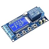
- Independent Parameters: OP/CL/LOP parameters can be modified and saved, and they are individual
- Auto Save: All setting parameters are automatically saved by power-fail
- LCD Display: the time delay relay module is designed with LCD display, can clearly and directly show the current mode and parameters
Relay, MOSFET, and contactor design
Separate the low-voltage driver, relay contacts, and downstream equipment in the design review. An IRLZ44N with a gate resistor, pulldown, and flyback diode can be a reasonable relay-coil driver when its gate voltage, current, dissipation, and wiring are verified. The diode belongs across the coil with correct polarity and short wiring.
- Check MOSFET ratings at the actual gate voltage, not only the headline current rating.
- Size the driver and traces for the relay’s measured coil current and worst-case temperature.
- Keep coil-return currents out of the logic ground path.
- Rate contacts for the actual voltage category, continuous current, inrush, switching frequency, and inductive interruption.
- For pumps, compressors, large blowers, or vacuums, use the PCB relay to operate a correctly rated contactor where necessary; do not infer motor suitability from a nominal relay label.
- Add suppression appropriate to the load: flyback for DC coils, and suitable snubbers or surge devices for AC inductive equipment.
- Provide fusing and overcurrent protection for each field circuit.
If mains wiring is present, maintain required creepage and clearance, barriers, protective-earth strategy, enclosure segregation, and local electrical-code compliance. A relay’s contact isolation is not the same as a fully isolated controller.
Isolation, grounding, and EMC
Optocouplers can reduce ground-loop and transient coupling, but they do not cure poor layout, inadequate power isolation, contaminated boards, or an unsuitable enclosure. Decide deliberately how protective earth, 12-volt negative, logic ground, shield drains, and isolated field returns relate. Isolation must include the power and signal paths, creepage, connectors, and mechanical barriers.
Put TVS devices close to exposed connectors, keep high-current and relay-contact routing away from displays and coin inputs, and use short, wide paths for load current. Test with the real motors, pumps, solenoids, and cable lengths; a quiet bench supply cannot reproduce field noise.
Do these 3 things before closing this tab:
1Repair Windows errors before they cause bigger problems2Fix the driver behind crashes, sound loss and screen glitches3Clear out junk files and repair common Windows errorsRank #4

- VERSATILE VOLTAGE & HIGH CAPACITY: Powered by 12V AC/DC input with a heavy-duty 16A output switch, designed to control high-power electrical equipment safely and efficiently.
- 28 ON/OFF PROGRAMMING SCHEDULES: Easily customize up to 28 daily and weekly ON/OFF timer settings to automate lighting, water heaters, pumps, solar systems, and agricultural controls.
- DIGITAL LCD DISPLAY & ACCURATE TIMING: Features a clear LCD screen for real-time monitoring and exact minute-level programming, ensuring precise execution of your scheduled automation.
- INTELLIGENT KEYPAD LOCK & MANUAL OVERRIDE: Equipped with an auto-keypad lock feature to prevent accidental setting changes and a manual override option for immediate ON/OFF switching.
- POWER OUTAGE MEMORY PROTECTION: Built-in battery backup preserves your programmed settings even during power interruptions, eliminating the need to re-program.
Enclosure and environmental protection
The assembly faces spray, condensation, detergent residue, conductive dirt, vibration, thermal cycling, and tampering. An enclosure’s advertised ingress rating applies to the complete installed assembly, including seams, locks, cable glands, vents, display windows, and buttons.
- Use retained, keyed connectors or removable terminal blocks so a board can be replaced without guessing every wire.
- Choose sealed, service-rated buttons and protect display openings from direct spray.
- Design cable glands and drip paths; do not let a vent become a water path.
- Validate heat rise in a sealed box under maximum relay and converter load.
- Consider conformal coating only after cleaning and drying the board, and keep coating off connectors, relays, switches, display contacts, adjustment points, and heat-transfer surfaces.
- Assess the coin acceptor separately; it may be the least weather-resistant component.
User interface and displays
Four TM1637 modules are convenient for a prototype, but long unshielded display wiring, sunlight, water ingress, and GPIO timing can make them poor field choices. Decide whether one larger multi-digit display, a sealed industrial display, a simple countdown plus service indicators, or a dedicated HMI gives customers and technicians clearer information.
Define visible states for idle, credit, selected service, remaining time, low credit, fault, and maintenance mode. A failed display should not leave outputs running or make the cabinet impossible to service; provide status LEDs or diagnostic indicators independent of the main display.
Independent reader supportYour contribution helps us test, update, and keep practical guides available for everyone.Firmware must be a state machine
Use explicit states rather than blocking delay loops:
Outdated Drivers Are Slowing You Down
One free scan finds every outdated or missing driver and matches the right update for your exact hardware.Free scan · exact hardware matchWindows Errors? Fix Them Before They Spread
Repair common Windows errors and clear accumulated junk for a smoother, more stable PC - no reinstall needed.Free scan · no reinstallBest Value

- 【Customizable and Versatile】Customize your exact schedule with up to 28 ON and 28 OFF settings per day or week. Featuring a precise 1-minute to 168-hour setting range and 15 different daily/weekly combinations, you can easily set specific routines for weekdays, weekends, or specific days to maximize efficiency
- 【WIDE RANGE OF APPLICATIONS】Specifically designed for 12V DC/AC systems, this robust 16A timer is a versatile solution for general electric appliances. It effortlessly automates RV water pumps, solar battery systems, auto fish feeders, and chicken coop doors, making it the perfect choice for a wide variety of indoor and outdoor DIY projects
- 【EASY TO PROGRAM】Programming this timer switch is a breeze with its easy-to-follow instructions and user-friendly LCD screen. It ensures a seamless setup experience, allowing you to effortlessly configure your desired settings. A step-by-step operation video is also available on the webpage for your convenient viewing
- 【POWER OUTAGE MEMORY】Rest assured that all your settings will be automatically saved in the event of a power outage. This ensures that your programmed schedules remain intact, providing uninterrupted functionality and reliable performance for your automated devices
- 【COMPACT & EFFICIENT】Measuring just 60x60x32mm, this compact timer module allows for a clean, professional panel-mounted installation in tight spaces. Operating with an ultra-low power consumption of less than 1W, it actively reduces energy waste while keeping your 12V appliances running automatically
- Idle
- Coin validation
- Credit available
- Service selected
- Service running
- Paused or interrupted
- Low-credit or expired credit
- Fault
- Maintenance/configuration
- Power-loss recovery
Implement a hardware watchdog, brownout handling, debounced buttons, coin-pulse plausibility checks, maximum run-time limits, persistent configuration, diagnostic counters, and safe output defaults during boot and reset. Enforce mutual exclusion where services cannot run together. Decide whether a power interruption forfeits time, pauses it, or resumes it, and store only the data needed to make that behavior reliable without wearing out flash memory.
The critical invariant is simple: an MCU reset must never leave a pump, motor, or solenoid unintentionally energized. On every reset, watchdog event, invalid configuration, and communication failure, drive outputs to a known safe state and require a deliberate restart.
PCB layout and manufacturability
- Partition logic, protected power, relay coils, and mains/load interfaces into identifiable zones.
- Place the fuse near power entry and TVS devices near exposed connectors.
- Observe creepage, clearance, board-edge spacing, and isolation-slot requirements for the voltage categories involved.
- Use locking or retained connectors, clear polarity marks, wire labels, and replaceable terminal blocks.
- Add test points, mounting-hole and protective-earth provisions, and a board-replacement procedure.
- Reserve keep-outs for conformal coating and maintain thermal paths for regulators and drivers.
- Run DRC and DFM checks, then inspect assembled boards before connecting field wiring.
Prototype-to-field test plan
- Bench function: verify coin values, credit arithmetic, service prices, display states, button behavior, and buzzer patterns.
- Fault injection: reverse the supply through a protected test setup, interrupt power, force a stuck coin signal, disconnect a display, and trigger watchdog resets.
- Load testing: operate the actual relay coils, contactors, solenoids, pumps, and motors with production-length cables and suppression.
- Noise testing: observe false pulses, brownouts, resets, and display corruption while loads start and stop.
- Environmental testing: test temperature rise, condensation, humidity, vibration, spray exposure appropriate to the installation, and long-duration cycling.
- Service testing: prove that a technician can isolate power, replace the board, identify every connector, and test each output individually.
Build or buy?
A custom PCB is justified when the service logic is stable, the board will be reproduced, wiring reduction matters, and the team can fund electrical, environmental, and load validation. It is premature to order an assembled batch from an untested prototype schematic.
Buy an industrial or purpose-built car-wash controller when downtime, installation liability, documentation, support, and compliance outweigh the savings of a custom board. A commercial controller may cost more and limit customization, but it can reduce the engineering risk of field wiring and maintenance.
What’s actually slowing this PC down?
Pick the symptom - the matching free tool is one click away.
Field-readiness checklist
- Electrical: fuse, reverse-polarity protection, surge suppression, filtering, verified regulator ratings, brownout behavior.
- Inputs: documented coin signal, protected conditioning, debounce, stuck-input detection, cable-noise testing.
- Outputs: verified MOSFET and relay ratings, flyback and load suppression, contactor assessment, per-circuit protection.
- Safety: intentional grounding, isolation boundaries, creepage and clearance, protective-earth and local-code review.
- Mechanical: complete installed ingress protection, sealed controls, retained connectors, thermal and condensation management.
- Firmware: state machine, watchdog, safe boot, power-loss policy, persistent settings, diagnostics, maximum run time.
- Service: labels, test points, output-test mode, event counters, replacement procedure, documented wiring.
- Validation: actual pumps and motors, worst-case cables, long-duration cycling, environmental and fault testing.
The Bottom Line
Use the published Carwash Vendo Timer design as a functional starting point, not as a production schematic. A field-ready controller needs protected power, conditioned or isolated inputs, properly rated contactors and suppression, deliberate grounding, a sealed serviceable enclosure, safe-state firmware, and testing with the real car-wash equipment. If those activities exceed the project’s resources, a commercial industrial controller is the lower-risk choice.
Quick Recap
Product prices and availability are accurate as of the date/time indicated and are subject to change. Any price and availability information displayed on Amazon at the time of purchase will apply.

