
Choose an SMD LED by the job it must do—not by package size or a single brightness number. A low-current indicator and a lighting emitter may both mount on a PCB, but they differ in optical requirements, drive circuitry, heat management, color control, and assembly needs. Treat the LED, driver, PCB, optics, enclosure, and manufacturing process as one system.
How indicator LEDs differ from lighting LEDs
An SMD (surface-mount device) LED is a packaged light-emitting diode designed for surface-mount assembly. The label describes its mounting style, not its performance: it covers tiny chip indicators, side-view and reverse-mount parts, RGB packages, mid-power white LEDs, and high-power emitters with thermal pads.
| Design concern | Indicator application | Lighting application |
|---|---|---|
| Primary optical target | Visibility, contrast, and luminous intensity in the viewer’s direction | Total luminous flux, efficacy, beam shape, and illumination uniformity |
| Typical drive approach | A resistor or low-current driver may suffice | Usually a constant-current driver with a designed thermal path |
| Package priority | Small size, low profile, lens, and viewing direction | Optical output, thermal resistance, and heat-spreader compatibility |
| Color specification | Recognizable, consistent status colors | CCT, CRI, chromaticity tolerance, and consistency across the array |
| Common optical aids | Light pipes, panel apertures, and diffusers | Reflectors, diffusers, lenses, and light guides |
A narrow-beam indicator can have a high millicandela (mcd) rating while illuminating only a small area. Lumens measure total visible output; candela and millicandela describe directional intensity. They are not interchangeable, so do not choose an area-lighting LED by the largest mcd figure.
For a status light, visibility at modest current, contrast, size, and a suitable viewing angle may matter more than total output. A miniature package can suit a compact panel; Kingbright describes its miniature 0202-class devices for status indicators and portable, appliance, smart-home, consumer-electronics, and healthcare applications (Kingbright miniature 0202 bi-color LED). A lighting design instead needs a defined output at the illuminated surface, plus adequate color and temperature performance.
What’s actually slowing this PC down?
Pick the symptom - the matching free tool is one click away.
#1 Best Overall
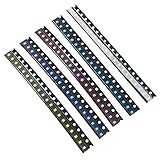
- Size: 0.08” x 0.05”;2.0 x 1.2 (mm)
- Colors:Yellow, Red, Blue, Green, White;5 Colors;Each Color 20pcs,Total 100pcs
- Forward Voltage / Current: W/B/G:3V-3.2V R/Y:2V-2.2V | 20mA (Each Color)
- High Efficiency: High Forward Surge Current Capability; High Temperature Soldering; Low Power Loss
- Application:SMD LED Kit Commonly Used in Vehicle Display (Dashboard) Lighting, DJ Equipment, Mobile Phones and Many Other Products
Choose package size and viewing geometry
Common package labels give a useful first estimate of footprint, not a substitute for the manufacturer’s mechanical drawing. Approximate metric dimensions are:
| Package designation | Approximate dimensions | Typical design note |
|---|---|---|
| 0201 | 0.6 × 0.3 mm | Very small; handling, inspection, and ESD controls are demanding. |
| 0402 | 1.0 × 0.5 mm | Compact indicator format. |
| 0603 | 1.6 × 0.8 mm | Common small indicator format. |
| 0805 | 2.0 × 1.25 mm | Larger footprint can make placement and inspection easier. |
| 1206 | 3.2 × 1.6 mm | More board area; check the actual optical and electrical design. |
| 2835, 3014, 3528, 5050 | Varies by manufacturer and construction | Often associated with lighting or multi-die formats; verify the drawing and thermal pad. |
A smaller package can save board area, but it usually leaves less room for optical output, heat spreading, and inspection. Package numbers do not guarantee a particular die arrangement, thermal capability, or footprint.
Match the emission direction to the product
- Top-view: emits upward from the board; often suitable for direct panel indicators or lighting arrays.
- Side-view: emits parallel to the board; useful for thin products and edge-lit displays.
- Reverse-mount: emits through an opening beneath the package, which can simplify some panel layouts.
- Flat or domed lens: changes the angular distribution and optical coupling; use the datasheet’s pattern rather than appearance alone.
Choose clear, diffused, or guided light
A water-clear lens can produce strong directional intensity but may create glare or a visible hot spot. A diffused lens softens the appearance and can improve uniformity, generally at the expense of peak intensity. A light pipe lets the LED sit away from the visible panel, but alignment and coupling introduce optical losses. For backlighting, a printed diffuser or light guide may be more important than the LED’s on-axis intensity. Evaluate the complete LED–PCB–enclosure stack.
Read the datasheet for operating conditions, not just headline values
Before comparing parts, separate recommended operating conditions from absolute maximum ratings. A maximum rating is a limit, not a target for continuous operation. Typical values are representative, not guaranteed production limits; check minimum and maximum values, bin specifications, and the conditions used for each measurement.
- Current and voltage: recommended forward current, maximum continuous current, pulse-current rating and pulse conditions, and forward-voltage range at the stated current and temperature.
- Optical output: luminous intensity or luminous flux, test current, viewing-angle definition, and measurement temperature.
- Color: peak or dominant wavelength for colored devices; chromaticity, correlated color temperature (CCT), color-rendering index (CRI), and tolerance for white devices.
- Protection and operating limits: reverse-voltage limit, operating-temperature range, ESD sensitivity, and any exposed-pad electrical connection.
- Manufacturing: land pattern, polarity marks, reflow profile, allowed reflow cycles, manual-soldering restrictions, and moisture-handling requirements.
Peak wavelength identifies the spectral peak; it is not always the best predictor of perceived color. For white-light designs, specify CCT and CRI as well as chromaticity tolerance. For colored indicators, verify the color at the actual operating current and viewing angle.
Design the drive circuit
An LED needs current control. Kingbright warns that small voltage changes without suitable current limiting can cause a large current surge, and advises individual series resistance for LEDs connected in parallel (Kingbright SMD LED application notes).
Rank #2

- 1206 SMD LED Kit: Color:Yellow, Red, Blue, Green, White;20pcs Per Color;Total 100pcs
- Forward Voltage / Current: W/B/G:3V-3.2V R/Y:2V-2.2V | 20mA (Each Color)
- Mini Size:Size:3.2 x 1.6 (mm) / 0.12 x 0.06 (inch) Small LED Chips
- High Efficiency:High Forward Surge Current Capability;High Temperature Soldering;Low Power Loss
- Application:Commonly Used in Vehicle Display (Dashboard) Lighting, DJ Equipment, Mobile Phones and Other Products
Calculate a resistor for a simple indicator
For one LED driven from a voltage source, a first-pass series-resistor calculation is:
R = (VS − VF) / IF
Check resistor dissipation using PR = IF2R.
For example, with a 5 V supply, a red LED assumed to have about 2 V forward voltage at the chosen operating point, and a 10 mA target, the calculation gives 300 Ω. A nearby 330 Ω standard value lowers current and adds margin. This is an illustration, not a universal red-LED value: use the selected part’s data and verify actual current.
Recommended Free Tools
For worst-case current, use the highest expected supply voltage and the lowest plausible forward voltage. Also check supply tolerance, resistor tolerance, temperature effects, transients, and the full LED forward-voltage distribution. If the supply varies widely or brightness must be tightly controlled, a resistor may not provide enough consistency.
Choose among resistor, linear, and switching control
| Drive method | Good fit | Trade-offs |
|---|---|---|
| Series resistor | Simple, low-current indicators with a stable or narrow-range supply | Inexpensive and easy to debug, but current changes with supply and LED voltage; excess voltage is wasted as heat. |
| Linear constant-current driver | Moderate power, low-noise operation, or simple dimming when voltage headroom is available | Stabilizes current but dissipates the voltage difference as heat; check dropout and thermal limits. |
| Switching constant-current driver | Higher power, long strings, battery-powered products, or wide input ranges | Can be more efficient, but adds components, switching noise, EMI, and layout and startup considerations. |
A resistor is often adequate for a modest indicator. For higher-output lighting, multiple LEDs, broad supply variation, or controlled dimming, a constant-current architecture is usually the safer starting point.
Do not share one resistor across parallel LEDs
LEDs with the same part number can have different forward voltages, so a parallel group may not divide current evenly. The lower-voltage device can take more current, become hotter, and take still more current. Use one resistor per LED, separate regulated channels, or properly designed series strings. If an array must match closely, specify suitable matching or bin controls as well.
Check reverse voltage and transients
LEDs generally have limited reverse-voltage tolerance. Consider reverse battery or connector insertion, power sequencing, inductive spikes, GPIO contention, ESD, and driver shutdown overshoot. Add circuit protection where the topology can reverse-bias or transiently overstress the LED; Kingbright specifically cautions against reverse voltage and power-up or power-down spikes in its application notes.
Free tools Windows power users keep installed
One-click scans. No signup required.
Rank #3

- 1200PCS SMD LED Diode Lights,50 pieces per color
- 6 Colors for Choose:Yellow, red, blue, green, white,Orange
- Size:0402 0603 0805 1206
- High Forward Surge Current Capability / High Temperature Soldering / Low Power Loss,High Efficiency
- Commonly used in Vehicle Display (Dashboard) Lighting, DJ Equipment, Mobile Phones and many other products.
Use PWM only after checking the full operating range
PWM dimming does not remove the need to respect peak-current limits. Check pulse width, repetition rate, duty cycle, driver response, and thermal conditions. At low duty cycles, a driver’s minimum pulse width can make brightness nonlinear; low-current operation can also change apparent color or consistency. Assess visible flicker, camera-band flicker, and audible noise in the actual product. If the design operates far below the datasheet’s main characterization current, consult the manufacturer or obtain low-current optical data. Kingbright notes that many examples use a 20 mA binning current and advises consultation for very low-current designs such as 2 mA; 20 mA is not a universal operating recommendation.
Control brightness and color consistency
Brightness depends on more than the LED’s nominal output: test current, temperature, viewing angle, lens transmission, diffuser, enclosure, and viewing position all matter. For an indicator, test visibility against the actual panel in expected ambient light. For illumination, measure light on the intended surface and assess uniformity, not just the emitter’s datasheet value.
LEDs may be sorted into bins for flux, color, and forward voltage. Lumileds explains that binning constrains variation in output, color point, and forward voltage, and that performance at application junction temperatures can differ from nominal 25°C measurements (Lumileds: Freedom from Binning). Where matching matters, specify permitted bins, approved substitutions, and lot traceability rather than assuming the same part number guarantees identical appearance. Kingbright also warns that mixed bins can produce visible intensity or chromaticity differences in its SMD LED application notes.
- For a multi-color indicator: check that each state is comparably visible; equal electrical current does not imply equal perceived brightness.
- For white lighting: define CCT, CRI, chromaticity tolerance (for example, an applicable SDCM or MacAdam-ellipse limit), and output at the relevant operating temperature.
- For low-current designs: use intensity-versus-current and color data at the actual operating point; do not assume a part’s main test condition predicts appearance at 1–2 mA.
- For parallel arrays: consider how forward-voltage, temperature, and bin variation affect both current sharing and visual matching.
LM-80 is a controlled method for measuring LED-component performance over time, including light output and color point; it is not, by itself, a guarantee of a complete luminaire’s service life. System life also depends on operating temperature, drive conditions, optics, materials, and construction. See Lumileds’ explanation of lumen maintenance and reliability.
Do these 3 things before closing this tab:
1Clear out junk files and repair common Windows errors2Scan for outdated or missing drivers - takes under a minute3Repair Windows errors before they cause bigger problemsDesign the thermal path before finalizing the lighting LED
For lighting, heat management should influence package and board choice from the start. Trace heat from the junction through the package, solder joint or thermal pad, PCB copper, vias or metal-core board, heat spreader or enclosure, and finally to ambient air. High temperature and excess current can reduce light output and reliability; Kingbright discusses these risks in its SMD LED application notes.
A first-order estimate is TJ = TA + PθJA, or, when the datasheet supplies suitable solder-point data, TJ = TS + PθJS. Here TJ is junction temperature, TA ambient temperature, TS solder-point temperature, P LED electrical power, and θ the relevant thermal resistance. Do not substitute θJA, θJB, and θJS without checking their definitions and test conditions. The manufacturer’s reference board may not resemble the final PCB.
Rank #4

- DiCUNO Wired Micro LED 100 pieces: Voltage for ten colors: Red, Yellow, Green, Orange (1.8-2.2V); Warm White, UV, Pink, White, Blue, Chartreuse (2.8-3.3V);Lead length: 6.3 inches (16cm); LED Size: 0.08”*0.05*0.05”. Amperage Capacity: 20mA; Average Brightness: 20-350mcd; Beam Angle: 120°
- The package will include 10 different colors micro LED in 10 units each color. Included colors: Red, Yellow, Green,Orange, Warm White, UV, Pink, White, Blue, Chartreuse.
- The 0805 micro LED diodes have positive and negative poles, solering LED, convenient to use.
- Wide Application: Ideal for model, science, DIY project lighting. Wire length could be easily shortened if you need shorter lead.
- Warranty: DiCUNO will offer 3-month refund and 1 year warranty to our customers. Any question required, please feel free to contact us.
- Use the specified thermal pad and enough copper area; add thermal vias or a metal-core board where the design requires them.
- Account for board thickness, copper weight, airflow, enclosure geometry, nearby heat sources, and neighboring LEDs.
- Measure temperature in the actual assembly and use the datasheet method for estimating junction temperature from solder-point data.
- Check the full power and thermal behavior of pulses: a permitted peak current does not automatically make a high-duty-cycle pulse thermally acceptable.
- Check whether an exposed pad is electrically connected and make the driver and PCB isolation compatible with that connection.
A small PCB inside a sealed enclosure can run much hotter than a datasheet test board, while a regulator or processor nearby can raise local temperature. Temperature differences across an array can show up as visible color variation.
Lay out the PCB and plan SMT assembly
PCB layout
- Use the manufacturer’s recommended land pattern and polarity orientation; verify them in the library and on the silkscreen.
- For a lighting emitter, provide the specified thermal pad and copper path. Keep switching-driver current loops short and follow the driver’s layout guidance.
- Keep hot components away from LEDs where possible, and include optical keep-outs so solder mask, silkscreen, or nearby parts do not obstruct the aperture.
- Align indicator packages with panel holes and light pipes, allowing for placement tolerance and enclosure assembly.
- For dense arrays, check copper and airflow for temperature gradients that could create brightness or color variation.
Reflow, ESD, and inspection
Use the individual LED’s current datasheet for peak temperature, time above liquidus, ramp and cooldown limits, allowed reflow cycles, and manual-soldering restrictions. Check moisture sensitivity and dry-pack instructions, flux compatibility, pickup-nozzle suitability, polarity recognition, and optical-surface cleanliness. Inspect for skew, tombstoning, solder bridges, and contamination; rework can damage the package, pads, or optical surface if it adds excessive heat or mechanical force.
Small LEDs require disciplined ESD handling. Kingbright recommends antistatic ionization during pick-and-place for 1608 metric devices and smaller and discusses handling practices in its SMD application notes. The ams OSRAM PointLED support page links to manufacturer guidance covering LED handling, ESD, dry pack, reflow, PCB technology, solder-point temperature measurement, thermal management, and photobiological safety.
Independent reader supportYour contribution helps us test, update, and keep practical guides available for everyone.Account for environment and mechanical stress
Humidity and corrosive environments
Moisture can contribute to corrosion, electrochemical migration, reduced insulation resistance, package cracking during reflow, and optical degradation. Follow storage and floor-life controls for the actual part. Kingbright warns that an LED that is off can still be exposed to voltage conditions associated with electrochemical migration, particularly in humidity; consult its application guidance for the relevant circuit and environment.
Some package encapsulants are permeable to gases, and contaminants such as hydrogen sulfide can attack silver-plated leadframes. Assess package suitability for sulfur compounds, industrial exhaust, rubber-processing fumes, coastal contamination, and cleaning chemicals. Manufacturer application notes discuss these risks; do not assume a general-purpose LED is suitable for every atmosphere.
Mechanical loads, UV, and blue light
Keep PCB bending, depanelization force, enclosure compression, and heavy-component stress away from small LED packages. Repeated or aggressive rework can crack a package or lift pads. For high-power blue, UV, and some white emitters, assess photobiological safety under the applicable product conditions rather than applying a blanket classification; manufacturer resources are available through the ams OSRAM support page.
The Tool Desk
Outbyte Driver Updater FREEScan for outdated or missing drivers - takes under a minuteDriver Scan →Outbyte PC Repair FREERepair Windows errors before they cause bigger problemsFix Now →Best Value

- Package Includes: 200pcs SMD LED diode lights, 5 colors,each color 40pcs
- A Variety of Colors are Available: Yellow, red, blue, green, white
- LED Diodes Chip Size: 3.2 x 1.6 (mm) / 0.12 x 0.06 (inch)
- Forward Voltage / Direct Current : DC 2 - 3 Volt 20 mA (Low Voltage for DIY PCB Circuit), High efficiency, Low power loss
- Wide Application: Commonly used in Vehicle Display (Dashboard) Lighting, DJ Equipment, Mobile Phones and many other products
Apply the criteria to common product designs
Front-panel and keypad indicators
Choose a viewing angle and lens that remain visible through the panel, then test contrast in both bright and dark environments. A diffused LED or light pipe can avoid a harsh point of light. For safety-relevant or accessibility-sensitive states, pair color with a symbol, text, position, or distinct blink pattern rather than relying on color alone.
Backlighting and small-area illumination
Specify output at the display or target surface and check uniformity through the real light guide, diffuser, and enclosure. Confirm that the LED’s emission direction and temperature behavior suit the optical stack; a high on-axis intensity alone does not guarantee even backlighting.
Industrial controls and consumer products
For simple status indication, prioritize readable states, supply tolerance, environment, package availability, and assembly controls. Industrial locations may need explicit checks for humidity, corrosive gases, vibration, and cleaning exposure. In compact consumer products, a miniature package may save space, but placement, ESD, optical alignment, and inspection capability still constrain the choice.
Automotive and safety-related equipment
Do not infer qualification from a package name or high-temperature rating. Verify explicit qualification for the exact part number, temperature grade, derating, failure modes, supplier change-control policy, and applicable end-product standards. Confirm that current manufacturer documentation supports the intended use.
RGB and decorative lighting
RGB provides flexible color states but needs three controlled current channels, software or control logic, calibration, and checks for unequal perceived brightness and thermal or optical interaction. Separate single-color LEDs may be simpler when distinct states or optical isolation matter. For lighting arrays, compare flux, efficacy, thermal resistance, color tolerance, and dimming behavior rather than selecting by package or unit cost alone.
Use this selection and validation checklist
- Define the job: decide whether the LED indicates a state, illuminates a surface, or must do both.
- Set the optical target: specify viewer position and visibility for an indicator, or flux, beam shape, and uniformity for lighting.
- Choose geometry: select package size, emission direction, lens, and any light pipe, diffuser, reflector, or guide.
- Set color requirements: define indicator colors or, for white lighting, CCT, CRI, chromaticity tolerance, and matching needs.
- Define electrical conditions: set continuous and peak current, supply range, PWM or multiplexing behavior, and protection needs.
- Select current control: compare resistor, linear, or switching drive against power, efficiency, noise, and dimming requirements.
- Check worst cases: calculate current across supply, forward-voltage, resistor, and temperature tolerances; check reverse voltage and transients.
- Calculate thermal margin: use the relevant datasheet thermal definitions and the actual PCB, enclosure, airflow, and nearby heat sources.
- Confirm manufacturing: verify footprint, polarity, reflow profile, moisture handling, ESD controls, inspection, and rework method.
- Control production variation: specify bins, traceability, lifecycle status, and approved alternates where needed.
- Validate the assembled product: test with the final enclosure and optics at supply and temperature extremes; measure light, color, temperature, flicker, startup, and transient behavior.
A useful prototype is the complete optical and thermal assembly, not a bare LED on a bench. Test the intended drive, PCB, enclosure, diffuser or light pipe, and production assembly process before locking the part and its approved alternatives.
Quick Recap
Manufacturer references
- Kingbright application-notes index
- Lumileds application briefs
- Nichia LED application-note library
- Cree LED precision dimming
Product prices and availability are accurate as of the date/time indicated and are subject to change. Any price and availability information displayed on Amazon at the time of purchase will apply.

