
What’s actually slowing this PC down?
Pick the symptom - the matching free tool is one click away.
Use the ESP32 to drive a MOSFET gate—not the vibration motor itself. For a small brushed eccentric-rotating-mass (ERM) motor, the reliable arrangement is a low-side 3.3 V logic-level N-channel MOSFET, an external motor supply, a flyback diode, a gate resistor, a gate pulldown, bulk decoupling, and a shared ground. The motor current then stays out of the ESP32 GPIO while PWM controls the perceived vibration.
Scope: this circuit is for brushed ERM motors
A coin or cylindrical ERM actuator is a small brushed DC motor with an off-center weight. It can be switched like other inductive DC loads. An LRA (linear resonant actuator) is different: it normally requires alternating drive and resonance control, so the single-MOSFET circuit below is not a complete LRA driver.
ESP32 variants expose PWM-capable peripherals, but those peripherals generate gate-control signals; they do not turn a GPIO into a suitable motor power output. Check the exact chip and board documentation before choosing a pin: Espressif ESP32 datasheet.
The reference circuit
                 +Vmotor
                    |
                    +---- ERM motor ----+---- Drain
                    |                   |
                    +------|<|----------+
                       flyback diode
                    cathode at +Vmotor
                    anode at drain

ESP32 GPIO ---- 100–330 Ω ---- Gate
                              |
                           47–100 kΩ
                              |
                             GND

MOSFET Source ---------------- GND
ESP32 GND -------------------- GND
Motor-supply negative -------- GND
Place a 47–470 µF bulk capacitor close to the motor-supply entry or driver board; add a 100 nF ceramic capacitor nearby when practical. The capacitor values are starting ranges, not substitutes for checking the motor’s current and the supply’s transient response.
#1 Best Overall

- High Current Dual MOSFET: Dual MOSFET design delivers up to 15 A continuous and 30 A peak at 400 W; strong drive for DC loads; ideal as a dc motor speed controller for robots, pumps, fans
- Wide Voltage and PWM Control: Accepts DC 5-36 V and logic 3.3-20 V; supports 0-20 kHz PWM for smooth ramping and precise speed or dimming; use as a pwm controller or motor controller in labs and builds
- Compact DIY-Friendly Board: About 1.34 x 0.67 x 0.47 in; small mosfet kit fits tight enclosures; simple two wire input and output layout integrates with microcontroller pins and breadboards
- Versatile Applications: Adjust DC motor speed, LED brightness and bulb dimming; drive micro pumps and solenoids; clean PWM input supports stable response and low heat for longer component life
- Rugged Reliability: Operates from minus 40 to 85 °C; dual MOSFET layout resists voltage spikes and load surges; dependable motor driver for industrial, automotive and DIY use
What happens electrically
- GPIO low: the MOSFET is off and the motor has no ground return.
- GPIO high: the MOSFET conducts from drain to source, completing the motor-supply circuit.
- When switching off, the diode carries the motor’s inductive current and limits the drain-voltage spike.
The diode is reverse-biased during normal operation: its cathode goes to the motor positive terminal and its anode goes to the motor negative/MOSFET drain. Reversing it can effectively short the supply through the diode.
Why the GPIO should not power the motor
Motor startup and stall current can be several times the running current. Connecting the winding directly to a GPIO can exceed output limits, cause brownouts and resets, inject brush noise into the 3.3 V rail, or permanently damage the pin. Wi-Fi and Bluetooth activity can make the failure intermittent because the ESP32’s own supply load changes.
A low-side N-channel switch is convenient because the gate voltage is referenced to ground. A high-side N-channel arrangement would require a gate voltage above the motor rail or an additional driver.
Rank #2

- Working voltage: DC 5V-36V, the trigger source: digital high-low (DC 3.3V - 20V), continuous current: 15A, maximum current and power: 30A, 400W, operating Temperature: -40-85℃, size: 1.34x0.67x0.47inch/34 x 17 x12mm (length x width x height)
- DUAL MOS DRIVE: The MOSFET motor board Utilizes dual MOS parallel connection with active output, featuring lower internal resistance, higher current, and robust power output (15A, 400W at room temperature), meeting the requirements of most devices
- WIDE VOLTAGE RANGE, PWM SUPPORT: With a working voltage range of DC 5V to 36V and compatibility with PWM signals, this PWM regulator control panel offers versatility in controlling devices. It accepts digital signals within the voltage range of DC 3.3V to 20V, making it suitable for use with micro controller IO ports, PLC interfaces, and other DC power sources
- COMPACT DESIGN, EASY INTEGRATION: Measuring just in 34x17x12mm (1.34x0.67x0.47inch), this high power PWM MOSFET driver module offers a compact form factor, facilitating effortless integration into various applications. Easily achieve control over high-power devices with this versatile and efficient module
- WIDELY APPLICATIONS: The MOSFET switch drive module is a versatile power control module that excels in a wide range of applications. Its design allows for precise control of high-power devices such as motors, LED lights, bulbs, micro-pumps, and solenoid valves. By accepting PWM signals, it can accurately regulate motor speeds, adjust lamp brightness, and more
Selecting the MOSFET for 3.3 V drive
“Logic-level” is not a sufficient specification by itself. Select from the manufacturer’s data at the voltage the ESP32 will actually provide. DigiKey explains why gate-voltage conditions matter in its MOSFET selection guide.
Free tools Windows power users keep installed
One-click scans. No signup required.
- RDS(on) at 2.5 V or 3.3 V: this determines conduction loss. A 10 V value does not prove low loss from an ESP32.
- Voltage rating: choose comfortable margin above the motor supply and any unclamped transient. A 20–30 V part is often practical for 3 V or 5 V motors when the diode and layout are correct.
- Current and thermal ratings: check running, startup, and stall current, then check package dissipation and PCB copper.
- Gate charge: modest charge is easier to switch at PWM frequencies. The AO3400A datasheet lists approximately 6–7 nC typical total gate charge under its test conditions.
- Pinout and body diode: verify the exact package drawing; drain, gate, and source order is not universal.
The AO3400A is a compact 30 V N-channel example with RDS(on) specifications at 2.5, 4.5, and 10 V, making its low-voltage data relevant to ESP32 designs: AO3400A datasheet. Its 2.5 V resistance is higher than the 4.5 V and 10 V figures, so calculate heating with the low-voltage specification.
Why VGS(th) is the wrong selection shortcut
Threshold voltage only indicates the beginning of conduction at a very small test current. It does not mean the device is a low-resistance switch. Use the specified RDS(on) at the intended gate voltage instead.
Rank #3

- MOSFET Switch Drive Module:for control motor speed light bulbs LED lights DC motors micro-pumps solenoid valves etc
- Size:34*17*12mm
- Voltage:DC 5-36V 15A Max:30A
- Operating temperature:-40-85℃
- Commodities include:6Pcs Trigger Switch Driver Module;6Pcs Heat Sink;1Pcs Screwdriver;10Pcs Male and Female Lines;10Pcs Male and Male Lines
Why IRF520 modules are often disappointing
Many inexpensive modules use the IRF520, whose useful performance is generally characterized at higher gate voltages. The DigiKey engineering discussion identifies it as unsuitable for the 3.3 V logic example: 3.3 V MOSFET selection guide. A module claiming “3.3 V compatible” still needs a real low-voltage RDS(on) specification.
An IRLZ44N is easier to prototype and heatsink in its TO-220 package, but it is physically excessive for most coin motors, and its listed drive specifications do not automatically guarantee low resistance at 3.3 V: IRLZ44N product page.
Recommended Free Tools
Choose the motor supply and protection parts
Use the motor manufacturer’s rated voltage. A motor marked 3 V should not be connected continuously to 5 V unless its manufacturer explicitly permits it. The supply must deliver startup and stall current without excessive sag. A separate motor rail is often the cleanest solution, but a shared supply can work when its regulator, wiring, and decoupling handle the transient.
Rank #4
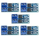
- Operating Voltage: DC 5V - 36V; The trigger source: digital high-low (DC3.3V - 20V); continuous current: 15A, enhance cooling conditions, the maximum current up to 30A; power: 400W.
- High Reliability, High Availability: It adopts double MOS parallel active output to show lower internal resistance,greater electric current and power. Besides it works at 15A,400W under common temperature which satisfies most devices usage and realizes the control of great power devices in a relaxed way.
- Supporting Multiple Signal Source Triggers: Can be connected microcontroller IO port, PLC interfaces, DC power, etc.
- PERFECT SUPPORT PWM: You can access the PWM signal, the signal frequency 0--20KHZ perfect support.
- WIDELY APPLICATIONS:You can control the output of power equipment, motors, light bulbs, LED lights, DC motors, micro-pumps, solenoid valves, etc., can input PWM, control motor speed, lamp brightness and so on.
- Flyback diode: a 1N400x is commonly adequate for small, relatively slow on/off motors. For low-voltage rails or faster PWM edges, select a suitably rated Schottky or fast diode and verify reverse voltage and current.
- Gate resistor: begin with 100–330 Ω to limit edge current and damp ringing.
- Gate pulldown: 47–100 kΩ keeps the MOSFET off while the ESP32 is booting or the pin is floating.
- Bulk capacitor: begin around 47–470 µF near the motor supply and increase it if startup causes visible voltage sag.
Adafruit’s motor-driver reference uses an N-channel MOSFET and 1N4007 diode; its documented topology is shown at Adafruit MOSFET Driver documentation.
On/off control
After verifying the wiring and pin assignment, a normal digital output is enough:
- Configure a safe, non-strap GPIO as an output according to the exact ESP32 board schematic.
- Write the pin low and confirm the motor is off.
- Write the pin high and confirm that motor current comes from Vmotor, through the motor and MOSFET, to ground.
- Switch low before disconnecting or changing the motor wiring.
Do not assume every numbered GPIO is interchangeable; boot strapping, flash connections, input-only pins, and board peripherals vary by ESP32 variant.
Best Value

- Dual parallel MOSFET design delivers ultra-low internal resistance and high current capacity. Supports continuous 15A at 400W under normal temperature, with peak current up to 30A when auxiliary cooling is applied. Built-in red LED indicator shows MOSFET conduction status.
- Wide operating voltage from DC 5V to 36V covers most common DC power systems. Perfectly supports PWM signal input from 0 to 20KHz, enabling precise motor speed regulation, LED brightness adjustment, and smooth dimming control without flickering.
- Versatile control board for DC motor speed control, LED strip and bulb dimming, micro-pump flow regulation, solenoid valve switching, and other high-power DC equipment. Suitable for robotics, smart home automation, lighting systems, and industrial control projects.
- Trigger source accepts digital high-low signals from DC 3.3V to 20V. Directly compatible with microcontroller IO ports including Arduino, Raspberry Pi, ESP32, ESP8266, and STM32, as well as PLC interfaces and standard DC power supplies. No additional level shifting required.
- Compact size of only 33.7mm x 16.9mm allows easy integration into space-constrained projects. Industrial-grade build quality ensures reliable performance. Package includes 6 modules for excellent project value and multi-device setups.
PWM for vibration intensity
Use the ESP32 LEDC peripheral for general PWM or MCPWM when you need motor-control-oriented features. See the LEDC documentation and MCPWM documentation. API names and setup calls differ between ESP-IDF releases and Arduino-ESP32 core generations, so pin the example to the version you build with rather than treating an unversioned snippet as universal.
Duty cycle changes average motor power, but not in a perfectly linear way. The motor may buzz or fail to start below a threshold, and mounting, battery voltage, temperature, and mechanical load alter the sensation.
- Apply a short full-duty startup pulse.
- Drop to the requested duty cycle.
- Keep a tested minimum running duty while the effect is active.
- Set duty to zero when the effect ends.
Start with a moderate PWM frequency and change it if audible whine or mechanical resonance appears. Higher frequencies can move switching artifacts out of the audible range, but increase switching transitions and can raise MOSFET losses. Recheck temperature after every frequency change.
Layout and grounding that prevent resets
- Connect ESP32 ground, motor-supply negative, and MOSFET source at a deliberate common point.
- Keep the motor-current loop (supply, motor, MOSFET, return) short and wide.
- Place the diode and bulk capacitor close to the motor connector or MOSFET.
- Keep high-current returns away from sensitive analog, reset, and RF paths.
- Treat a breadboard as a prototype only; its contacts and long jumpers add resistance and inductance.
Troubleshooting guide
| Symptom | Checks |
|---|---|
| Motor does not run | Measure motor voltage; confirm common ground, MOSFET pinout, diode polarity, GPIO assignment, supply current capability, and RDS(on) data at 3.3 V. |
| Weak vibration | Measure voltage directly across the motor while running. Check supply sag, wiring drop, low duty cycle, starting threshold, and partial MOSFET enhancement. |
| ESP32 brownouts or resets | Separate or improve the motor rail, add bulk capacitance, shorten returns, and prevent brush current from sharing sensitive ground paths. |
| MOSFET runs hot | Measure startup/stall current; recalculate I²R loss using low-voltage RDS(on); inspect PWM frequency, duty cycle, copper area, and package limits. |
| MOSFET fails at turn-off | Look for a missing or reversed diode, inadequate diode ratings, long inductive wiring, supply spikes, or insufficient MOSFET voltage margin. An oscilloscope across drain-source can reveal the transient. |
| Audible whine | Try another PWM frequency and inspect mounting resonance, while checking motor performance and MOSFET temperature again. |
One motor, many motors, and when to use a driver IC
Several independent ERM motors
Use one MOSFET and one diode per motor, with a separate GPIO/PWM channel. Size the supply for simultaneous startup current and distribute motor power in a star-like arrangement where practical. For many channels, an integrated protected low-side array or motor driver can simplify layout.
Do these 3 things before closing this tab:
1Fix the driver behind crashes, sound loss and screen glitches2Repair Windows errors before they cause bigger problems3Scan for outdated or missing drivers - takes under a minuteBidirectional or regulated operation
A single low-side MOSFET switches only one direction. Use an H-bridge for reversal. Choose a dedicated motor or haptic driver when you need repeatable current-controlled intensity, active braking, diagnostics, thermal or overcurrent protection, coordinated channels, or LRA resonance control. TI’s brushed-DC driver catalog is a starting point: TI motor drivers.
Quick Recap
Practical component choices
| Option | Best use | Limitations |
|---|---|---|
| Adafruit MOSFET Driver | Beginner breadboard prototypes; documented 3–20 V logic and 3–30 V load ranges, with AO3406 and 1N4007. | Single channel and physically larger than a custom PCB solution; no precision current regulation. |
| AO3400A | Compact custom boards and small ERM loads. | Requires correct PCB copper, thermal analysis, and careful pinout verification. |
| IRLZ44N | Through-hole prototypes and higher-current loads where size is acceptable. | Oversized for coin motors; 3.3 V low-loss operation must be verified from the exact datasheet. |
| Dedicated haptic or motor-driver IC | Production designs, multiple actuators, regulation, diagnostics, or LRA control. | More circuitry and cost than a simple on/off switch. |
Design checklist
- Confirm the actuator is a brushed ERM and record rated, startup, and stall current.
- Select a MOSFET with RDS(on) specified at the ESP32’s actual gate voltage.
- Use a motor supply at the rated voltage with adequate transient current.
- Fit the correctly oriented diode, gate resistor, pulldown, and bulk capacitor.
- Connect grounds deliberately and keep the high-current loop short.
- Test startup duty, PWM frequency, supply sag, MOSFET temperature, and ESP32 stability under worst-case simultaneous loads.
Product prices and availability are accurate as of the date/time indicated and are subject to change. Any price and availability information displayed on Amazon at the time of purchase will apply.

