
Free tools Windows power users keep installed
One-click scans. No signup required.
iTechGuides is reader-supported. When you buy through links on our site, we may earn an affiliate commission. As an Amazon Associate I earn from qualifying purchases. Learn more
Factory automation works best when motion devices, controllers, networks, safety functions, maintenance data, and energy measurements are designed as one system. Standards can provide common models and communication rules, but they do not by themselves guarantee that devices from different vendors will work together, that a safety function will meet its required integrity, or that a plant will save energy. Those outcomes depend on application requirements, supported implementations, and system-level verification.
What should a factory automation design solve first?
Start with the production task and its constraints, not with a protocol or product. A motion axis, its controller, its network path, and any safety function all have timing and behavior requirements. Maintenance and energy systems, in turn, need data that is meaningful in the context of the machine and its operating state.


Use these questions to define the problem before selecting equipment or network architecture:
- Motion: Which drives, converters, positioning devices, servos, and encoders must communicate, and what control profiles and update timing does the application require?
- Connectivity: Which traffic needs deterministic behavior, what network convergence is required, and how will mixed-vendor devices be verified?
- Safety: What hazards and safety functions must be addressed, and what certified devices, communication architecture, and system validation are required?
- Maintenance: Which condition data is available, how reliable and contextualized is it, and how will detection be validated against maintenance decisions?
- Energy: What must be measured, at what granularity, against which baseline and operating conditions, and who can act on the findings?
These criteria expose dependencies early. For example, a drive interface that provides useful operational data may support maintenance analysis, but that does not establish that the data is sufficient to predict a particular failure. Likewise, putting controls and other traffic on a converged network does not establish that the deployed system will meet a particular latency target.
#1 Best Overall
How can motion devices and controllers interoperate?
Define the motion interface and timing needs
Motion interoperability spans more than a servo and a controller. The OPC Foundation’s Field Level Communications initiative identifies standard drives, frequency converters, positioning drives, servo drives, and motion encoders within the motion working group’s scope. The relevant interface must still be checked against the actual controller, device capabilities, required control behavior, and timing needs.
OPC UA Field eXchange (OPC UA FX) is an OPC Foundation initiative to extend OPC UA to field-level automation. Its factory-automation work includes a shared base model for controllers and field devices, standardized profiles such as I/O, motion control, and functional safety, device information models, Time-Sensitive Networking (TSN) support, and conformance units and certification procedures. These features provide a framework for describing and testing interfaces; they are not proof that any particular controller-and-drive combination is compatible.
Check device semantics, not just connectivity
A device that can exchange data is not necessarily interoperable for the intended motion task. Verify that both ends support the needed profile and represent the relevant functions and characteristics consistently. Also confirm the behavior that matters to the application, including timing and diagnostics, rather than treating a successful network connection as sufficient evidence.
Rank #2
The OPC Foundation’s PROFINET Drives information model describes how drive characteristics and functionality are represented. Its specification notes that sensor data gathered during normal operation may provide a basis for analytics that identify patterns associated with approaching failures. That is a possible use of operating data, not a guarantee that a specific fault can be detected accurately or in time.
What does TSN add to industrial connectivity?
TSN is an approach to converged industrial networking in which traffic requirements can be addressed through selected network features and procedures. IEEE/IEC 60802-2026 defines TSN profiles for industrial automation networks, specifying selected features and procedures for bridges, end stations, and local area networks. The IEEE lists the standard as active and gives its publication date as June 29, 2026.
A TSN profile does not automatically make a deployed, mixed-vendor network interoperable or guarantee a particular latency. Verify the required features and behavior across the actual end stations and bridges, including the controller, drives, switches, and other networked equipment. Check conformance evidence and test the planned topology under representative traffic and operating conditions.
Rank #3

- Output type:NO(Normally Open) PNP.
- Product type: Inductive Proximity Sensor Switch.
- Detect Object: Iron. Detect Distance:2mm±10%.
- Working Voltage: DC 6-36V. Wire Type: 3 Wire.
- Package include: 5 pcs LJ8A3-2-Z/BY Inductive Proximity Sensor Switch.
When evaluating an industrial Ethernet switch or other network infrastructure, confirm its environmental suitability, supported protocols and features, timing behavior, security requirements, and fit with the intended topology. The standards establish networking scope, not the compatibility or suitability of a particular product.
Do these 3 things before closing this tab:
1Repair Windows errors before they cause bigger problems2Fix the driver behind crashes, sound loss and screen glitches3Clear out junk files and repair common Windows errorsHow should functional safety be handled over networks?
Network selection alone does not establish functional safety. Begin with the hazard analysis and required safety functions, then select an appropriate safety architecture and devices whose implementation is suitable for those requirements. Validate the complete system rather than relying on a standard-device connection or a network label.
OPC UA safety communication
IEC 62541-15:2025 specifies OPC UA mechanisms for transmitting safety-relevant messages and provides guidance for developers and assessors. It is intended for safety devices. IEC explicitly cautions that implementing the document in a standard device does not qualify that device as a safety device; the system’s resulting Safety Integrity Level (SIL) claim depends on how the document is implemented within the system.
Rank #4

- Infrared Light Emitting Diode: The light source is an infrared light emitting diode with low power consumption and long service life.
- 4 Meter Detection Range: The sensor has a 4m detection range, interference by visible light small, easy to assemble, easy to use and so on.
- 1.93 Meter Cable: Use a long cable, which is convenient to your wiring arrangements.
- NPN Output: The output mode of photoelectric sensor (photoelectric switch) is NPN.
- Wide Used: This photoelectric switch sensor can be widely used in auto door, car garage, robot obstacle avoidance, assembly line and many other automated products.
Black-channel principles
IEC 61784-3:2021 describes common principles for transmitting safety-related messages on distributed fieldbus networks in accordance with IEC 61508. These principles use a black-channel approach: safety communication is addressed in a way that does not depend on the underlying transmission channel itself being safety-rated. This does not remove the need to choose suitable safety devices, implement the safety layer correctly, or validate the system against its requirements.
How can condition data support maintenance?
Predictive maintenance depends on more than collecting sensor readings. Data needs sufficient quality and machine context to support an analysis, and any detection method needs validation against the failures and maintenance decisions that matter in the plant.
The Tool Desk
Outbyte PC Repair FREEClear out junk files and repair common Windows errorsFree Scan →Outbyte Driver Updater FREEScan for outdated or missing drivers - takes under a minuteDriver Scan →IEC 63270-1:2025 provides guidance on predictive-maintenance functional structures, procedures, methods, interfaces, and data requirements for industrial automation. It identifies condition monitoring as a possible important input. The standard does not promise a particular failure-prediction rate, reduction in downtime, or financial return.
Best Value
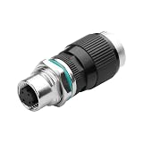
- Waterproof M12 4-Pin Female to RJ45 Adapter, providing seamless data transmission between industrial Ethernet systems and standard network devices, compatible with Cat5e and Cat5 networks, with a maximum data rate of 10 Gb/s
- IP68 M12 4-Pin to RJ45: A highly elastic rubber gasket and clamping nut provide waterproof and dustproof protection. Rated current: 2A; rated voltage: 30V; operating temperature: -25°C to +80°C
- Plug-and-play; installation and removal require no tools. The M12-to-RJ45 Ethernet adapter quickly connects field devices to terminal interfaces in seconds. The built-in design prevents cable kinking and ensures ease of use
- The RJ45 to M12 industrial Ethernet adapter features gold-plated brass pins to ensure superior connection performance. It incorporates a threaded locking mechanism with a shock-resistant locking design and a 12mm threaded connector. 100% shielding ensures stable and reliable data and signal transmission.
- Widely used in micro-sensors, industrial cameras, electric bicycle packaging, labeling and logistics, factory automation, and fieldbus modules.
Before operationalizing a condition-monitoring or analytics workflow, define which equipment and conditions are covered, what data is available during normal operation, how it is contextualized, and how a suspected pattern will be checked. Decide how maintenance personnel will use an alert and how results will be assessed; availability of a data model alone does not validate detection performance.
Independent reader supportYour contribution helps us test, update, and keep practical guides available for everyone.How can energy management produce useful, measurable action?
Energy efficiency claims need a defined measurement boundary, a baseline, and operating context. A plant-wide total may conceal differences between equipment, production cells, or operating states, while a measurement without a practical route to action may not identify an achievable improvement.
The OPC UA Energy Consumption Management specification provides interoperable semantics for energy-management systems and describes a workflow: analyze current consumption, identify potential savings, then realize selected savings. Its model is designed to scale from standalone devices through machines and production cells to whole factories and plants.
Quick wins for a faster PC:
Fix the driver behind crashes, sound loss and screen glitchesFind Drivers →Repair Windows errors before they cause bigger problemsFix Now →Use that progression to connect measurement to decisions. Establish what is being measured and at what level, compare consumption under relevant operating conditions, identify opportunities, then assess outcomes after action. The specification does not establish a savings figure. Official standards material does not provide a factory-wide percentage for energy savings, downtime reduction, or motion efficiency that can be applied across applications.
How do you turn standards into a verified design?
- Document the application: List motion tasks, required timing, network traffic, safety functions, maintenance needs, and energy measurements. Record the operating context that affects each requirement.
- Map interfaces to requirements: Identify the controller and device profiles, data models, and network features each function needs. Treat OPC UA FX and TSN support as implementation details to verify, not as a blanket compatibility claim.
- Separate safety decisions: Use hazard analysis to establish the required safety functions and architecture. Confirm device suitability, communication implementation, and system-level validation for the required SIL claim.
- Plan data use: Specify the condition and energy data needed, its source and context, and the maintenance or operational decision it is intended to support. Define how its quality and usefulness will be evaluated.
- Verify components and the integrated system: Check conformance evidence and controller-device compatibility, then test the real topology and application behavior against requirements. Include representative traffic, operating conditions, diagnostics, and failure handling as appropriate.
- Measure outcomes against a baseline: For maintenance and efficiency initiatives, record the baseline and conditions, then assess actual results. Do not infer prediction accuracy or savings from standards support alone.
Which design is best?
There is no universal best protocol, drive, switch, safety architecture, maintenance method, or energy strategy established by these standards. The appropriate design is the one that meets the application’s motion, timing, safety, data, and measurement requirements—and whose implementation can be verified in the intended system.
| Design area | Decision criteria | Evidence to verify |
|---|---|---|
| Motion integration | Supported control profiles, timing needs, device semantics, and required diagnostics | Controller-and-device support for the relevant profiles and functions; tested application behavior |
| Connectivity | Deterministic traffic needs, network convergence, interoperability, and diagnostics | Required TSN features and procedures across devices and bridges; conformance evidence and representative network tests |
| Functional safety | Hazards, required safety functions, architecture, and integrity requirements | Suitable safety devices, correct communication-layer implementation, and system-level validation |
| Maintenance | Available condition data, its context and quality, workflow, and detection performance | Relevant data and a validated method for the intended failure and maintenance use |
| Energy management | Measurement coverage and granularity, baseline, operating context, and ability to act | Comparable measurements and observed outcomes after selected actions |
The OPC Foundation’s Field Level Communications page reports a steering committee of 23 member companies, and its factory-automation page reports more than 60 joint working groups defining semantics through OPC Companion Specifications. These are activity counts, not measures of adoption, interoperability, or performance.
Quick Recap
Product prices and availability are accurate as of the date/time indicated and are subject to change. Any price and availability information displayed on Amazon at the time of purchase will apply.

