
What’s actually slowing this PC down?
Pick the symptom - the matching free tool is one click away.
iTechGuides is reader-supported. When you buy through links on our site, we may earn an affiliate commission. As an Amazon Associate I earn from qualifying purchases. Learn more
Scientists account for polar motion by using Earth-orientation parameters (EOPs) to transform coordinates consistently between Earth-fixed and inertial reference frames. That matters for precise satellite positioning, orbit determination, and geodetic work. In earthquake studies, however, the signal of interest is usually movement of the crust—such as displacement across a fault—not motion of Earth’s pole. Polar motion belongs to the coordinate framework used to interpret measurements; it is not the earthquake displacement itself.
What is polar motion?
The International Earth Rotation and Reference Systems Service (IERS) defines polar motion as “the motion of the Earth’s pole with respect to the ITRS,” the International Terrestrial Reference System. In practical terms, Earth’s rotation axis shifts relative to the frame used to describe positions fixed to Earth. That shift is one part of the Earth-orientation information needed to relate terrestrial coordinates to celestial or inertial ones.
Earth’s wobble has more than one timescale
IERS identifies two main components: the Chandlerian free motion, with a period of approximately 430 days, and an annual motion. There are also sub-daily variations associated with ocean tides and periodic gravitational torques. IERS-distributed polar-motion values do not include those sub-daily variations. For applications that require them, users add the appropriate IERS Conventions model after interpolating the EOP values to the date of interest.
How does polar motion affect GPS and satellite measurements?
Polar motion affects the orientation used when converting coordinates, not the physical location of a receiver or satellite. A station position expressed in an Earth-fixed frame cannot be treated as an inertial position without accounting for Earth orientation. EOP provide part of that connection. NASA’s Jet Propulsion Laboratory describes its Earth-orientation files as calibrations used to rotate station locations from an Earth-fixed frame to an inertial frame.
#1 Best Overall

- HOBBY MODEL KIT – Unassembled model packed in an envelope with easy to follow instructions. Ideal for ages 14 and up.
- NO GLUE OR SOLDER NEEDED – Parts can be easily clipped from the metal sheets. Tweezers are the recommended tool for bending and twisting the connection tabs.
- VOYAGER – 1.5 Sheet Model with a moderate difficulty level. Assembled Size: 1.38 x 1.77 x 6.70 inches.
- FROM STEEL SHEETS TO 3D – Pop out the pieces and connect using tabs and holes. Includes illustrated instructions.
- HIGHLY DETAILED ETCHED MODEL – Display your 3D model once completed - collect and build them all.
Frame consistency matters
For precise work, it is not enough to apply an EOP file in isolation. The reference-frame realization and Earth-rotation conventions must match those to which the EOP refer. JPL notes that this consistency is necessary when using EOP to obtain centimeter-level inertial station locations. A mismatch between frame conventions or correction models can undermine the precision the transformation is meant to provide.
Choose EOP data for the job
IERS rapid-service products provide Earth-orientation determinations and predictions. Prediction is important where users need orientation values before final observations are available, including satellite-based positioning and navigation; IERS also identifies deep-space navigation and instrument pointing as applications. Depending on the product, EOP solutions may be rapid, ultra-rapid, or final, with different update latency and prediction content. Select the product and reference-frame realization appropriate to the analysis rather than assuming all files have the same status or coverage.
Rank #2

- Model Kit
- May Require Paints and Glues to Assemble
- Accurate Scale Model
- Detailed Instructions Provided
- Decals/Transfers Included
NASA Earthdata documents IGS orbit-combination products that include EOP solutions. These products and IERS services support the broader task of keeping satellite orbits and ground-station coordinates consistent with Earth’s changing orientation. The operational EOP products serve a different purpose from the IERS C01 long-term series, which is intended for historical context rather than rapid operational updates.
Does polar motion affect earthquake measurements?
Earthquake geodesy measures deformation of the crust. USGS describes GPS and satellite imaging methods such as interferometric synthetic aperture radar (InSAR) as tools for measuring crustal motion and coseismic displacement. In a GNSS/GPS analysis, scientists observe common satellites at multiple stations and compare station positions over time to resolve motion associated with faults. USGS earthquake-imaging work also uses Sentinel-1 InSAR and optical correlation to derive surface-displacement observations and estimate earthquake source properties.
Rank #3

- HOBBY MODEL KIT – Unassembled model packed in an envelope with easy to follow instructions. Ideal for ages 14 and up
- NO GLUE OR SOLDER NEEDED – Parts can be easily clipped from the metal sheets. Tweezers are the recommended tool for bending and twisting the connection tabs
- APOLLO CSM – 3.5 Sheet Model with a challenging difficulty level. Assembled Size: 5.07 L x 2.28 W x 3.45 H inches.
- FROM STEEL SHEETS TO 3D – Pop out the pieces and connect using tabs and holes. Includes illustrated instructions
- HIGHLY DETAILED ETCHED MODEL – Display your 3D model once completed - collect and build them all
Keep the two motions separate
Polar motion is a change in Earth’s orientation relative to the terrestrial frame; coseismic displacement is movement of the ground at and around a fault. EOP can matter when coordinates or orbits must be expressed consistently across terrestrial and inertial frames, but it is not the fault movement being measured. The available USGS, IERS, and NASA descriptions do not establish that every earthquake-processing workflow applies an identical polar-motion correction, or that polar motion is a routine standalone correction to an InSAR interferogram.
What do GNSS and satellite imaging measure in earthquake studies?
| Method | Observed quantity | How it contributes to earthquake analysis | Earth-orientation role |
|---|---|---|---|
| GNSS/GPS | Station positions or displacement time series. | Comparing positions over time can reveal fault motion and coseismic offsets. USGS describes observations of common satellites at multiple stations as part of resolving station movement. | EOP are relevant when positions or satellite orbits are transformed between terrestrial and inertial frames; the precise workflow depends on the analysis. |
| InSAR and optical image correlation | Radar line-of-sight or image-correlation surface-displacement observations. | Satellite imagery can map surface deformation and support estimates of earthquake source properties. USGS describes use of Sentinel-1 InSAR and optical correlation for this purpose. | The cited USGS materials do not establish polar motion as a routine standalone correction to an InSAR interferogram. |
These methods provide different kinds of observations and coverage: GNSS uses station measurements over time, while satellite imaging depends on image acquisitions and processing. The cited sources do not provide a controlled head-to-head performance comparison, so neither method should be described as universally more accurate or useful.
Rank #4

- HOBBY MODEL KIT – Unassembled model packed in an envelope with easy to follow instructions. Ideal for ages 14 and up.
- NO GLUE OR SOLDER NEEDED – Parts can be easily clipped from the metal sheets. Tweezers are the recommended tool for bending and twisting the connection tabs.
- JAMES WEBB SPACE TELESCOPE - 2.75 Sheet Model with a moderate difficulty level. Assembled Size: 4.13 L x 2.75 W x 2.75 H inches. 1:221 Scale. 62 Pieces
- FROM STEEL SHEETS TO 3D – Pop out the pieces and connect using tabs and holes. Includes illustrated instructions.
- HIGHLY DETAILED ETCHED MODEL – Display your 3D model once completed - collect and build them all.
Which Earth-orientation data should a reader expect?
For satellite or geodetic analysis, first identify the coordinate frames, reference-frame realization, and Earth-rotation conventions required by the product. Then choose an IERS or IGS-supported EOP product whose determination status and prediction content suit the observation dates and latency needs. If the application requires sub-daily polar-motion effects, check whether they are included; IERS-distributed values omit them, so the relevant conventions model must be added after interpolation.
Recommended Free Tools
For long-term historical context, IERS’s C01 series is distinct from rapidly updated operational products. Its metadata describes observations beginning in 1846, with sampling at 0.1-year intervals for 1846–1889 and 0.05-year intervals from 1890 onward. The IERS metadata accessed on October 1, 2026 listed data through September 12, 2026; that endpoint is metadata-dependent and should be checked against the current series before use.
Quick Recap
Best Value
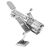
- HOBBY MODEL KIT – Unassembled model packed in an envelope with easy to follow instructions. Ideal for ages 14 and up.
- NO GLUE OR SOLDER NEEDED – Parts can be easily clipped from the metal sheets. Tweezers are the recommended tool for bending and twisting the connection tabs.
- HUBBLE TELESCOPE – 1 Sheet Model with a moderate difficulty level. Assembled Size: 3.00 x 2.00 x 2.50 inches.
- FROM STEEL SHEETS TO 3D – Pop out the pieces and connect using tabs and holes. Includes illustrated instructions.
- HIGHLY DETAILED ETCHED MODEL – Display your 3D model once completed - collect and build them all.
Product prices and availability are accurate as of the date/time indicated and are subject to change. Any price and availability information displayed on Amazon at the time of purchase will apply.

