
A microcontroller simplifies a fluorescent ballast by coordinating lamp preheat, ignition, steady-state current regulation, dimming and fault response in firmware. It does not replace the high-voltage power stage: the ballast still needs a suitable inverter, feedback circuitry and protection. The main design choice is whether to build that control around a general-purpose MCU or use an integrated ballast controller with more of the power-control functions built in.
Why a fluorescent lamp needs a ballast
A fluorescent lamp is difficult to start and has a negative-resistance operating characteristic: once its arc is established, simply applying voltage does not provide stable current regulation. The ballast must first create the conditions for ignition, then limit and regulate current while the lamp operates.
ON Semiconductor’s application note AN1543/D identifies the central jobs as providing startup voltage across the lamp electrodes, maintaining constant current in steady state and keeping the circuit stable under fault conditions. A practical design also has to address power-factor correction (PFC), total harmonic distortion (THD), radio-frequency interference (RFI) and electrical safety.
What the microcontroller does
The MCU turns ballast operation into a sequence of controlled states, with measurements and feedback guiding transitions. It supervises the power electronics; it is not itself the source of the lamp’s ignition voltage or the component that carries lamp current.
#1 Best Overall
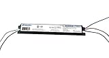
- FEATURES: Engineered to operate 1 or 2 T8 fluorescent lamps—including F32T8, F25T8, F17T8, and F40T8. Its parallel lamp connection offers better performance with mismatched lamps and independent lamp operation. Perfect for retrofits or replacements. This lamp ballast delivers instant start technology that ensures fast lamp ignition and energy savings. Compact and lightweight, it features standardized mounting dimensions and pre-wired leads for quick and easy installation.
- Certified to the Highest Safety Standards: UL/935 Listed (Class P, Type 1 Outdoor), cUL (CSA C22.2 Certified), RoHS Compliant, Type HL Rated, featuring Inherent Thermal Protection. Our ballast undergoes rigorous third party testing to ensure maximum fire and electrical safety—protecting both your property and your peace of mind. It contains no PCBs, Class P, Type 1 Outdoor) for safety and compliance. Designed for remote mounting up to 18 feet, it includes 18 AWG leads.
- Optimized 120V Ballast for Residential and Light Commercial Installations - Purpose-built for single-voltage 120V operation, this ballast eliminates the complexity of multi-voltage wiring found in commercial 120–277V models. Ideal for homes, offices, and small facilities, it simplifies installation by removing voltage selection guesswork and ensures faster, error-free installation. Delivers reliable startup and energy-efficient performance for F32T8 or F25T8 lighting systems.
- QUALITY AND DURABILITY: Designed to withstand extreme environments, this ballast operates reliably in ambient temperatures from -18°C (0°F) up to an impressive 104°C (219°F). This electronic ballast incorporates premium internal components and solid-state design to reduce heat and extend product lifespan. Each unit undergoes rigorous quality testing to ensure superior performance in demanding lighting environments.
- Equivalent to a wide range of ballasts: ICN-2P32-N, ICN-2P32-SC, REL-2P32SC, REB2P32SC, GE232120RES, GE232120N, QT2X32T8120ISNSC, B232I120RESA, B232I120RESG, B232I120RHA, B232I120RESA, B132IUNVHPN, B132IUNVHPB, B232I120RHA, HL232RIS12W, B232I120RA-A, RLQ-120-TP, E2/32IS/120SC; E-758-F-232, GE-232-120-N; B232I120RH-A, VE232120MIP, KTEB-232LBF-1-TP-PIC-EV
- Preheat: Control the lamp-electrode heating interval before attempting to strike the arc.
- Ignition: Change inverter operation to produce the conditions needed to start the lamp, while monitoring whether ignition succeeds.
- Run: Use feedback and adjustments such as inverter-frequency control to regulate lamp power or current as operating conditions change.
- Dim and communicate: Map dimming commands to inverter control and handle an input or protocol such as DALI when the design supports it.
- Diagnose and protect: Monitor signals such as lamp current and bus voltage, detect faults such as a missing lamp or failed ignition, and shut down or respond according to the design.
In Microchip’s description of fluorescent lighting, the ballast first supplies the energy to kick-start the electrical-gas reaction, then regulates current to a normal operating level. Firmware makes the timing and control behavior configurable, but safe response still depends on the complete hardware-and-software design.
Common control architectures
General-purpose MCU with external power stages
In this approach, the MCU controls separately implemented PFC and resonant-inverter stages. Microchip’s PIC16F1508 DALI ballast proof of concept uses active PFC and an LCC resonant inverter. Its MCU peripherals include PWM, a numerically controlled oscillator (NCO), a DAC, a configurable logic cell and comparators; the design uses NCO frequency control for smooth digital dimming.
Rank #2
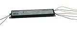
- FEATURES: Engineered to operate 3 or 4 T8 fluorescent lamps—including F32T8, F25T8, F17T8, and F40T8. Its parallel lamp connection offers better performance with mismatched lamps and independent lamp operation. Perfect for retrofits or replacements. This lamp ballast delivers instant start technology that ensures fast lamp ignition and energy savings. Compact and lightweight, it features standardized mounting dimensions and pre-wired leads for quick and easy installation.
- Certified to the Highest Safety Standards: UL/935 Listed (Class P, Type 1 Outdoor), cUL (CSA C22.2 Certified), RoHS Compliant, Type HL Rated, featuring Inherent Thermal Protection. Our ballast undergoes rigorous third party testing to ensure maximum fire and electrical safety—protecting both your property and your peace of mind. It contains no PCBs, Class P, Type 1 Outdoor) for safety and compliance. Designed for remote mounting up to 18 feet, it includes 18 AWG leads.
- Optimized 120V Ballast for Residential and Light Commercial Installations - Purpose-built for single-voltage 120V operation, this ballast eliminates the complexity of multi-voltage wiring found in commercial 120–277V models. Ideal for homes, offices, and small facilities, it simplifies installation by removing voltage selection guesswork and ensures faster, error-free installation. Delivers reliable startup and energy-efficient performance for F32T8 or F25T8 lighting systems.
- QUALITY AND DURABILITY: Designed to withstand extreme environments, this ballast operates reliably in ambient temperatures from -18°C (0°F) up to an impressive 104°C (219°F). This electronic ballast incorporates premium internal components and solid-state design to reduce heat and extend product lifespan. Each unit undergoes rigorous quality testing to ensure superior performance in demanding lighting environments.
- Equivalent to a wide range of ballasts: ICN-4P32-N, ICN-4P32-SC, ICN4P32N, ICN4P32SC, KTEB-432-UV-IS-N-P, QTP4X32T8/UNV ISN-SC, REL-4P32-SC, REB4P32N, E4/32IS/120SC,E-758-F-432-SC, REB4P32SC, GE432-120RES-DIY, B432I120RH-A, B432I120RESA, GE-432-120-N
This arrangement suits products that need firmware flexibility—for example, a shared control platform for different lamp ratings or control interfaces. The designer remains responsible for integrating the power stages, sensing, drive circuitry, protection and compliance work.
MCU-controlled PFC boost and half bridge
Microchip’s AT89RFD-10/EVLB002 reference design pairs a PFC boost converter with a variable-frequency half-bridge inverter. The 2006 Microchip/Atmel guide specifies a 90–265 VAC, 50/60 Hz input and support for up to two 18 W T8 lamps. It describes MCU timing, regulation and diagnosis across that universal-input range.
Free tools Windows power users keep installed
One-click scans. No signup required.
Rank #3

- electric-household-fan-replacement-parts
- Commercial brand: Philips Advance
- Import From: Mexico
This is a concrete example of an MCU supervising a multi-stage ballast, not a general guarantee that any MCU or half-bridge design supports those lamps or input conditions.
Integrated ballast controller
An integrated ballast controller combines functions that otherwise would be implemented across separate control circuitry. Infineon’s ICB2FL03G combines a PFC controller, half-bridge inverter control, a state machine, a digital PFC loop and a high-voltage level-shift driver. ST describes integrated startup, programmable preheat and ignition, timing and protection functions intended to reduce external component count.
Rank #4
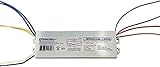
- FEATURES: The Robertson RSW234T12120 electronic ballast is designed to optimize fluorescent lighting systems, supporting both 1 lamp or 2 lamp T8 and T12 configurations. This lamp ballast features rapid start functionality, flicker-free performance, quiet operation, and enhanced energy efficiency—making this ballast a smart choice for any lighting replacement ballast unit. Compact form factor ideal for space-constrained retrofits.
- Certified to the Highest Safety Standards - UL Listed (Class P, Type HL, Type CC, Type 1 Outdoor), CSA Certified (cUL). RoHS Compliant, Meets FCC Part 18 (Class B) for EMI and RFI consumer limits, Conforms to ANSI standards C82.11 and C62.41. Features thermal protection, surge resistance, and end-of-lamp-life safety shutoff.
- Robust Operating Performance: Robertson /developed/patented End-of-lamp-life protection prevents lamp damage, Internal surge protection safeguards against voltage spikes, Inherent thermal protection ensures safe operation under varying temperatures.
- EQUIVALENT TO: REL2S40SC, R2S40-1-TP, R2S40TP, B234SR120M, B240R120HP, GE240RS120, GE240RS120DIY, QTP2X40T12120RSNSC, KTEB-240-1-TP, WHCG9-127-T12-RS and other ballasts that drive 2 ea F40T12 lamps
- With over 75 years of ballast design and manufacturing experience, Robertson is a trusted U.S.-based brand offering technical support and top-quality products. We sell only what we design and manufacture ourselves—no outsourced rebrands, no compromises.
Integration can reduce the amount of control circuitry and firmware a designer must assemble, but the exact lamp range, dimming interfaces and protection behavior depend on the selected controller and its implementation. Check the relevant device documentation rather than assuming that every integrated controller includes the same functions.
Independent reader supportYour contribution helps us test, update, and keep practical guides available for everyone.General-purpose MCU or integrated ballast controller?
The choice is mainly a trade-off between flexibility and integration. The sources describe representative devices and designs, not a like-for-like test or a universal bill of materials, so several cost and implementation comparisons cannot be quantified.
Quick wins for a faster PC:
Clear out junk files and repair common Windows errorsFree Scan →Fix the driver behind crashes, sound loss and screen glitchesFind Drivers →Repair Windows errors before they cause bigger problemsFix Now →Best Value

- Made in Mexico
- Package length : 18.0"
- Package width : 18.0"
- Package height : 21.0"
| Design consideration | General-purpose MCU | Integrated ballast controller |
|---|---|---|
| Control flexibility | Firmware can adapt timing, lamp variants, dimming curves and interface behavior; Microchip describes firmware modification and intelligent control in its lighting architecture. | Functions are organized around ballast control; ST describes programmable preheat and ignition, but the extent of configurability depends on the device. |
| External control circuitry | Requires the designer to implement and integrate the needed PFC, inverter control, sensing and drive functions. The PIC16F1508 example uses external active-PFC and LCC-inverter stages. | Can reduce external component count. Infineon’s ICB2FL03G integrates PFC and half-bridge control plus a high-voltage level-shift driver; ST describes integration of startup, timing and protection functions. |
| High-voltage drive | Not established as built into the general-purpose MCU in the cited PIC16F1508 example; the power-stage drive must be handled by the overall design. | Infineon’s ICB2FL03G includes a high-voltage level-shift driver. |
| PFC | Implemented in the system design. Microchip’s PIC16F1508 proof of concept uses active PFC and reports a PFC figure of 0.95 or better, and 0.98 at full load. | Infineon’s ICB2FL03G includes a PFC controller and digital PFC loop. |
| Dimming and DALI | The PIC16F1508 proof of concept is a DALI ballast and uses NCO frequency control for smooth digital dimming. | Specific DALI or dimming support is not stated in the cited Infineon and ST descriptions. |
| Lamp compatibility | Depends on the power-stage design and firmware. The AT89RFD-10/EVLB002 guide specifies up to two 18 W T8 lamps; that rating belongs to the reference design. | Specific compatible lamp ratings are not stated in the cited Infineon and ST descriptions. |
| Fault handling | Firmware can implement diagnosis and shutdown, using suitable sensed signals and hardware safeguards. Microchip’s AT89RFD-10 guide describes diagnosis. | ST describes integrated protection functions; the cited description does not enumerate every fault response. |
| Compliance workload | The designer must validate the complete ballast against applicable electrical-safety, PFC, THD and RFI requirements; an MCU does not provide compliance by itself. | Integration does not establish compliance for the finished ballast. The cited descriptions do not state a compliance outcome for a complete product. |
| Development cost and serviceability | Comparative cost and serviceability are not stated in the cited Microchip sources; firmware flexibility may help support product variants. | Comparative cost and serviceability are not stated in the cited Infineon and ST sources; fewer external control components may simplify the control section. |
Choosing a topology for a digitally controlled ballast
Start with the lamp and product requirements, then choose the control architecture. The controller cannot compensate for a resonant power stage or protection scheme that is unsuitable for the lamp and operating range.
- Specify the lamp and input conditions. Identify lamp type and rating, whether one or multiple lamps are required, input-voltage range, and any dimming or communications needs. Treat the AT89RFD-10/EVLB002’s 90–265 VAC, 50/60 Hz and up-to-two-18 W-T8 figures as that reference design’s stated capability, not a generic ballast specification.
- Select the power-stage topology. Decide how PFC and the resonant inverter will be implemented. The documented examples include active PFC with an LCC resonant inverter in Microchip’s PIC16F1508 proof of concept, and a PFC boost converter with a variable-frequency half bridge in the AT89RFD-10/EVLB002 design.
- Map control functions to hardware. Determine which timing, feedback, frequency control, sensing, drive and protection functions belong in the MCU, external circuitry or an integrated ballast controller. Confirm the actual peripheral and driver requirements against the chosen device documentation.
- Define startup and fault behavior. Specify preheat, ignition, run and shutdown transitions, including what happens when a lamp is absent, ignition fails, or a monitored electrical condition leaves its allowed range. Set safe limits in the complete circuit design rather than relying on firmware alone.
- Validate dimming and compliance. Confirm the intended input protocol and dimming range, then evaluate the finished ballast for electrical safety, PFC, THD and RFI. A control feature or published reference design is not evidence that a different product meets those requirements.
When a PIC16F1508 is a relevant starting point
The PIC16F1508 is a concrete MCU option to examine when the goal is a digitally controlled fluorescent ballast with DALI: Microchip identifies it in a ballast proof of concept using active PFC, an LCC resonant inverter and NCO-controlled dimming. The page reports PFC of 0.95 or better and 0.98 at full load for that proof of concept; those figures describe the referenced design, not every implementation using the MCU.
It is a starting point for evaluating control peripherals and reference-design architecture, not a drop-in ballast controller. Confirm that the device, external power stage and sensing and protection circuits fit the target lamp and requirements before committing to a design.
Quick Recap
Product prices and availability are accurate as of the date/time indicated and are subject to change. Any price and availability information displayed on Amazon at the time of purchase will apply.

