
A wound-field DC dynamo is not safe simply because its electrical load is small. At rising engine speed, a lightly loaded dynamo can develop excessive voltage unless its field current is controlled. For a vintage 6 V system, retain a correctly matched battery-and-regulator arrangement or use a field regulator confirmed for the exact dynamo; do not choose a replacement by voltage rating alone.
What “low load” means for a dynamo
A dynamo is a DC generator. In a wound-field design, a stationary field winding creates the magnetic flux, while the rotating armature generates electrical output. Common terminal labels include D+ for output, DF for the field connection, and D− for the return, but vintage wiring conventions vary. A cut-out relay disconnects the battery when dynamo voltage falls below battery voltage; a field resistor and regulator help control excitation.
At a given speed and field current, the dynamo generates an electromotive force. A useful simplified relationship is E ∝ speed × field flux, while terminal voltage is approximately V = E − IloadRinternal. Neither relationship is perfectly linear: magnetic saturation, brush and commutator drops, temperature, wiring resistance, and other effects matter.
The important distinction is that a low load limits current demand; it does not necessarily limit open-circuit voltage. A substantial load produces voltage drop and other effects that can reduce terminal voltage. With little load, those effects are reduced. If field current remains high as speed rises, voltage can exceed the nominal system level and damage ignition parts or overheat dynamo windings.
The Tool Desk
Outbyte PC Repair FREERepair Windows errors before they cause bigger problemsFix Now →Outbyte Driver Updater FREEFix the driver behind crashes, sound loss and screen glitchesFind Drivers →#1 Best Overall
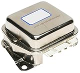
- professional, premium aftermarket replacement
- provides the performance and dependability you expect from acdelco
- manufactured to meet expectations for fit, form, and function
- Fit type: Vehicle Specific
Why the original battery and regulator worked together
The battery was more than a convenient load. It supplied energy when the dynamo produced little at starting or low RPM, could energize the field before generation was established, and helped stabilize voltage and suppress ripple. The cut-out prevented the battery from discharging back through a slow or stopped dynamo. The regulator controlled the dynamo’s output, principally by changing field current.
Removing the battery therefore changes startup, energy storage, and voltage stabilization. Some regulators are designed to work without a battery in specified circumstances; others require one. “The dynamo can run without a battery” does not establish that the ignition will start or operate normally without one.
A permanent-magnet alternator is different: its magnetic field cannot be turned down electrically, so regulators commonly rectify and shunt or switch excess output. A wound-field dynamo offers a direct control point—the field current—and normally should be regulated there.
Rank #2

- Fitment: Replacement for Chrysler, Dodge, and Mopar round back alternators. Ideal for restoring vintage electrical systems
- Part Number: Chrysler: 1889960, 2095700, 2098300, 3000074, CH-524, CH-531 Aftermarket: ACR6000, IPM 1C-6050, J&N 230-10001, 230-10006, REGITAR C524M, VRC524, WAI 35-300, 35-300-1
- Confirm Compatibility:Please double-check the listed fitment information year, make, model to ensure this part is correct for your car
- Match Your Original Part Visually:In most cases, you can compare our product's detailed pictures and specifications with your existing part to confirm it is a direct match
- Attention: Please check whether the compatibility information matches your vehicle model
Why an ignition coil is not a fixed resistor
A points ignition coil’s primary has resistance and inductance, and the points repeatedly switch it. With the points closed, current rises during the dwell period; when they open, the collapsing magnetic field produces the spark. The current waveform and average demand depend on coil resistance and inductance, dwell, engine speed, contact condition, ignition layout, and whether one or more coils are used.
For scale, a continuously energized 3 Ω primary at 6 V would approach 2 A by a simple V/R estimate; a 1.8 Ω primary would approach 3.3 A. These are steady-state resistive estimates, not the average current of a working ignition system. Rising supply voltage can still increase current during dwell and increase coil heating, so a modest ignition load is not protection against overvoltage.
How field-current regulation works
Reducing field current reduces magnetic flux and, at a given speed, generated EMF. Original mechanical regulators used contacts to switch between field conditions, often including a resistance path; a separate cut-out handled battery isolation. Electronic regulators can replace vibrating contacts with transistor switching. Boyer Bransden describes its regulator as switching the field above 500 times per second and varying the duty ratio in response to dynamo voltage.
Rank #3

- FITMENT 1:Voltage Regulator for Motors AMX 1978-1979 Concord 1978-1979 Gremlin 1976 Hornet 1976-1977 Matador 1976-1978 Pacer 1978-1979 Spirit 1979 De Tomaso Pantera 1971-1974 Ford Aerostar 1986-1989 Club Wagon 1963-1964 Cougar 1985-1986 Country 1963-1974, 1987-1991 Custom 1964-1977 E-series 1963-1967, 1969-1987, 1990 Elite 1975-1976 Escort 1981-1985, 1987-1989 EXP 1982-1985, 1987-1988 F-100 1963-1983 F-150 1975-1992 F-250 1963-1992 F-350 1963-1992 F-450 1988-1992 Fairlane 1963-1970 Fairmont 1978-1983 Falcon 1962-1970
- FITMENT 2:Voltage Regulator Replacement for Galaxie 1963-1974 Granada 1975-1982 GT 1968 LTD 1965-1991 Maverick 1970-1977 Mustang 1964-1986 Pinto 1971-1980 Ranch Wagon 1968-1974 Ranchero 1962-1979 Ranger 1983-1989 Station Bus 1962-1965 Taurus 1986-1988, 1990 Tempo 1984-1985 Thunderbird 1962-1964, 1966-1990 Torino 1968-1976 Jeep Cherokee 1976-1977 CJ 1976-1977 J-Series 1976-1977 Wagoneer 1976-1977 Lincoln Continental 1963-1980, 1982-1991 Mark III 1968-1971 Mark IV 1972-1976 Mark V 1977-1979 Mark VI 1980-1983 Mark VII 1984-1992 Town Car 1982-1990 Versailles 1977-1980
- FITMENT 3:Voltage Regulator Replacement for Mercury Bobcat 1975-1980 Brougham 1967 Caliente 1964-1967 Capri 1966-1967, 1979-1986 Colony Park 1963-1974, 1987-1991 Comet 1965-1969, 1971-1977 Commuter 1964-1968 Cougar 1967-1988 Country Cruiser 1963 Cyclone 1964-1971 Grand Marquis 1975-1991 LN7 1982-1983 Lynx 1981-1985 Marauder 1963-1970 Marquis 1967-1986 Meteor 1963 Monarch 1975-1980 Montclair 1964-1968 Montego 1968-1976 Monterey 1963-1974 Park Lane 1964-1968 Sable 1986-1990 Topaz 1984-1985 Villager 1963-1967 Voyager 1966-1967 Zephyr 1978-1983
- IGNITION CONTROL MODULE TROUBLE CODE SUPPORT include P0350, P0351, P0352, P0353, P0354, P0355, P0356, P0357, P0358, P0359, P0360, P0361, P0362. These generic OBD-II codes are related to ignition coil primary/secondary circuit faults and can be associated with ignition control system operation. For reference only. Actual diagnostic results may vary by vehicle, engine configuration, and operating condition.
- Attention: Please check whether the compatibility information matches your vehicle model before purchasing
“Shorting the field” is not a universal wiring instruction. Depending on the dynamo and regulator, control may involve grounding or disconnecting the field, inserting resistance, recirculating field current, or switching a transistor in the field path. Follow the wiring information for the exact topology and polarity; do not infer the method from terminal labels alone.
The role of the original field resistor
In the MZ-style arrangement reported in the All About Circuits discussion, the factory field resistor is approximately 4.4 Ω. In that particular mechanical-regulator system it is described as part of the intermediate field-current arrangement, not as a standalone replacement for regulation. Depending on the design, a field resistor can provide minimum excitation, smooth transitions between regulator states, and help maintain generation.
What’s actually slowing this PC down?
Pick the symptom - the matching free tool is one click away.
A modern regulator may require that resistor to be removed or disconnected. Powerdynamo specifies this for its R81. Leaving an original resistor in a circuit without checking the replacement regulator’s instructions can prevent correct control or cause abnormal operation.
Rank #4

- Fitment: Compatible with Dodge W250 Ramcharger Dakota 1970-1993 Plymouth Gran Fury Trailduster Duster
- Part Number: 12336870 2-VR1 27-1690 C603B VR125T VR733 5234625 4091050 3755850 5K5 R296 4111990 C603Z 12338616 12336870 4379100 12338616 3755960 KVR176A 1119165 VR38 VR733VC 2-604 1V1081 VR38SB 4379225 VR1 3438150 RAA1049 1119180 177-0645 2-VR1
- Confirm Compatibility:Please double-check the listed fitment information year, make, model to ensure this part is correct for your car
- Match Your Original Part Visually:In most cases, you can compare our product's detailed pictures and specifications with your existing part to confirm it is a direct match
- Attention: Please check whether the compatibility information matches your vehicle model
Regulation methods and their trade-offs
| Method | Controls the field? | Battery requirement | Heat and main risk | Best suited to |
|---|---|---|---|---|
| Original mechanical regulator and cut-out | Yes, through its specified contact and resistance arrangement | Retains the battery-based system functions | Contact wear and arcing; requires correct adjustment and inspection | Originality-focused restoration with the correct battery and wiring |
| Compatible electronic field regulator | Yes | Product-specific; verify batteryless startup and operation | Electronics can be damaged by wrong polarity, field load, transients, or heat | A dynamo whose field resistance, topology, voltage, and polarity match the regulator |
| Capacitor plus a suitable regulator | Only if the regulator controls the field | A capacitor can support transients but does not supply battery-equivalent sustained energy | Wrong capacitance, voltage rating, polarity, or lack of field control can leave excursions unaddressed | Systems where the regulator specifies a capacitor or where ripple support is needed |
| Zener or shunt regulator | No; it diverts excess output rather than reducing field excitation | Depends on the overall system | Excess energy becomes heat; device and wiring can be stressed at high RPM | A carefully engineered fallback when field control is not practical |
| Unregulated operation | No | May run under some conditions, but no battery function is assured | Voltage can rise with speed; apparent success at one operating point proves little | Not a sound general operating strategy |
A shunt regulator can be engineered for a particular application, but it is usually a poor first choice for a wound-field dynamo: it leaves the field excited and converts excess output into heat. A capacitor can reduce ripple or provide brief transient energy, but it does not inherently regulate voltage, guarantee regulator startup, or reproduce the battery’s sustained energy storage and low-impedance reference.
Batteryless operation needs more than a capacitor
Without a battery, the regulator must cope with startup, low-speed field supply, ripple, intermittent ignition current, and rapid voltage changes as RPM rises. It also needs a defined response when field drive is switched off, including management of the field winding’s stored energy. A batteryless setup may need a specified excitation source or controlled startup circuit.
Boyer Bransden says its regulator can run lighting and a horn directly from the dynamo without a battery, but its published information also says ignition cannot be fed at kick-start speeds because voltage is insufficient. That is a product-specific claim for its stated application, not proof that every dynamo or batteryless ignition system will behave the same way.
Best Value
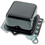
- Replacement Part Numbers: 1119512, 1119515, 1119519, 156960, 191818, 8273, 8-273, 967867R91, 9L7309, 9L7648, D630, D635, D663, 1119506
- Condition: New; Voltage: 12V; Mounting Hardware Included: No; Number of Pieces: 1; Country of Origin: CN; Notes: Transpo; Solid state circuit; OE appearance
- Compatible With Cadillac Fleetwood Base, 60 Special, 75 Limousine 7.7L 1968-72; Compatible With Buick Electra 225 Custom Hardtop, 225 Hardtop, 225 Custom 7.5L 1970-72; LeSabre Base, Base Hardtop, Custom 5.7L 1968-72; LeSabre Base, Base Hardtop, Custom 7.5L 1970-72; Compatible With Chevrolet Camaro Base, RS 4.1L 1967-72; Camaro Base, RS 5.0L 1969-72; Camaro RS, SS 5.7L 1967-72
- See Product Description for Additional Specifications
Check regulator compatibility before buying
A “6 V regulator” label is not enough. Match the regulator to the actual dynamo and installation:
- Dynamo type and brushes: Confirm it is a wound-field DC dynamo and whether the regulator supports its two-brush or three-brush arrangement.
- Field topology and terminals: Establish how the field is connected and which terminal is grounded. Do not rely on labels alone.
- Field resistance: Measure the disconnected field winding cold, using a meter suitable for low resistance and compensating for lead resistance.
- Polarity and system voltage: Match positive or negative earth and the regulator’s 6 V or 12 V configuration.
- Current and power limits: Observe both the dynamo’s limits and the regulator’s ratings; a regulator’s maximum rating does not increase the dynamo’s safe output.
- Battery and startup requirements: Confirm whether the regulator will start and regulate without a working battery.
- Factory resistor: Check whether it must remain, be bypassed, or be disconnected.
- Protection and installation: Follow the specified fuse, grounding, transient protection, and mounting guidance. Avoid a hot, enclosed, vibration-prone location unless the manufacturer permits it.
Two published 6 V regulator specifications illustrate why resistance matters. DVR2 specifies a field resistance greater than 2.5 Ω. Powerdynamo’s R81 specifies at least 2.5 Ω, negative ground, and disconnection of the stock regulating resistor. A field measured at approximately 1.7 Ω is below those stated minima; treat either unit as incompatible unless its manufacturer confirms the application in writing. R81’s application information also calls for a working 6 V battery for flawless operation in the specified arrangement.
Boyer Bransden lists its dynamo regulator primarily for Lucas E3 two-brush systems, with positive- and negative-earth versions. It is an example of field regulation, not an automatic recommendation for a Bosch/MZ dynamo. Confirm the exact field and wiring match before considering it.
What the MZ/Bosch-style example does—and does not—show
An All About Circuits discussion describes a particular 1960s motorcycle setup as a Bosch-style, 6 V, approximately 60 W dynamo with D+, DF, and D− terminals, points-and-coil ignition, a field winding reported at approximately 1.7 Ω, and a factory field resistor reported at approximately 4.4 Ω. The machine was being used without the conventional battery and lighting load, and its owner reported needing temporary excitation because residual magnetism was weak. These are details reported in that case, not universal specifications for every Bosch or MZ dynamo.
Quick wins for a faster PC:
Clear out junk files and repair common Windows errorsFree Scan →Fix the driver behind crashes, sound loss and screen glitchesFind Drivers →Repair Windows errors before they cause bigger problemsFix Now →A later post in the same discussion calls the unit a two-brush dynamo and mentions a possible 90 W transient maximum, while correcting an earlier polarity statement. That output figure is forum testimony, not an independently verified manufacturer rating. Use the original service information and measurements for the particular machine rather than treating these figures as a specification sheet.
Measure and test in stages
- Identify the circuit: Find the service diagram and confirm brush count, field connections, polarity, terminal functions, coil arrangement, and whether the field resistor is internal or external.
- Inspect the dynamo: Check brush length and spring pressure, commutator, bearings, insulation, continuity, and isolation to the case. Repair mechanical or insulation faults before testing regulation.
- Measure the field: Disconnect it and measure cold resistance with a low-resistance-capable meter, subtracting lead resistance. A 1.7 Ω field connected directly across 6 V would draw about 3.5 A by V/R; actual current depends on temperature and circuit arrangement. Compare the measurement with the regulator’s published range before installation.
- Verify polarity and excitation: Follow the exact service-manual procedure for direction of rotation and field flashing. If residual magnetism is absent, use only the specified excitation method and polarity; improvised flashing can establish the wrong polarity or damage components.
- Instrument the system: Monitor dynamo voltage, field current, ignition-coil supply voltage, RPM, and component temperature. A meter may miss brief spikes; an oscilloscope or transient-capable logger is more informative during development.
- Test the operating envelope: Check cranking, idle, moderate and maximum intended RPM, points-open and points-closed conditions, and hot and cold operation. Assess disconnected-load behavior only with a controlled setup and suitable overvoltage protection.
- Set stop limits in advance: Stop if voltage exceeds the safe limit for the system, field current exceeds the regulator or winding limit, or the regulator or dynamo heats abnormally. Do not leave a small dynamo fully fielded and unloaded at high RPM longer than its service procedure allows.
A single successful start shows only that the system produced enough power under that condition. It does not demonstrate safe voltage at high RPM, with the points open, under an intermittent load, or after a regulator fault.
Quick Recap
Choose the approach that fits the restoration
- For an original restoration: The most defensible route is the original battery, cut-out, mechanical regulator, and field resistor in the factory arrangement, maintained to the service instructions.
- For a discreet electronic conversion: Use a regulator whose maker confirms the exact dynamo topology, field resistance, polarity, battery requirement, and resistor treatment.
- For batteryless racing or a low-load prototype: Use a custom field-control solution designed around measured winding resistance and validated across the RPM range, including startup and fault conditions. Temporary excitation may be required.
- For a proposed zener conversion: Treat it as an engineered heat-dissipation design, not a generic 6 V part swap. A wound-field regulator is usually the more direct control method.
Sources
- All About Circuits: Dynamo regulation under low loads — the reported application details.
- All About Circuits discussion, page 2 — follow-up application claims and polarity correction.
- Dynamo Regulators FAQ — mechanical regulator and cut-out background.
- DVR2 product information and DVR2 data sheet — published compatibility and installation specifications.
- Powerdynamo R81 application information — field resistance, polarity, resistor, and battery requirements.
- Boyer Bransden dynamo regulator information and installation and technical data sheet — stated application and operating claims.
Product prices and availability are accurate as of the date/time indicated and are subject to change. Any price and availability information displayed on Amazon at the time of purchase will apply.

