
Quick wins for a faster PC:
Fix the driver behind crashes, sound loss and screen glitchesFind Drivers →Repair Windows errors before they cause bigger problemsFix Now →You can build this kind of counter by combining a tube-specific high-voltage flyback supply, a circuit that turns each Geiger–Müller discharge into a conditioned logic pulse, and a counter that sends event totals to LabVIEW. A 2017 Electronic Design project used a Silego GreenPAK for voltage regulation and pulse counting, then transferred counts over SPI and a UART-to-USB bridge. Its reported target of at least 450 V is a design target for that project—not a universal tube setting or a calibration result.
How the flyback Geiger counter works
A Geiger–Müller (GM) tube contains low-pressure gas between an anode and cathode. When ionizing radiation initiates an avalanche inside the tube, the resulting discharge briefly changes the electrical signal. The counter detects that event, converts it into a pulse that low-voltage logic can handle, and increments an event count.
In the Electronic Design project, the flyback converter supplies the tube’s high voltage. A resistor divider feeds a GreenPAK comparator, and the GreenPAK adjusts PWM duty cycle to regulate the output. The project detects the discharge-related change, counts pulses digitally, and communicates the count to a LabVIEW graphical interface through SPI and a UART-to-USB bridge.
GM tubes can respond to alpha, beta, gamma, and X-ray radiation, but the tube does not identify which type produced a count. Window construction affects which radiation can reach the sensitive volume; tube selection must therefore match the intended use.
The Tool Desk
Outbyte PC Repair FREEClear out junk files and repair common Windows errorsFree Scan →Outbyte Driver Updater FREEScan for outdated or missing drivers - takes under a minuteDriver Scan →#1 Best Overall
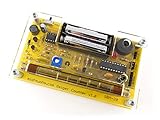
- Kit includes all components needed to build a working Geiger counter, including a high quality printed circuit board, sensitive Geiger-Muller tube, laser-cut acrylic case, and 2xAAA batteries.
- Included SBM-20 Geiger tube is sensitive to beta and gamma radiation. LED and piezo speaker alert you to detected radioactivity.
- Mute button for silent operation.
- 100% Open Source Hardware (OSHW). Full schematics, PCB layout, and source code available online.
- Expansion headers allow you to connect your kit to other devices, such as Arduino and Raspberry Pi. Supports data logging. Can be connected to a laptop or desktop PC using a USB-serial cable (not included).
Choose the tube before setting the voltage
Use the selected tube’s datasheet to determine its operating bias and other electrical requirements. Analog Devices describes common GM-tube bias as 250–500 V in its 2024 documentation. Its CN0536 reference design provides an adjustable 280–500 V supply with an SI-29BG example tube. The Electronic Design project from 2017 configured its flyback supply to reach at least 450 V. These are different design contexts, not interchangeable settings.
Tube operating voltage, plateau behavior, sensitivity, dead time, and window construction vary. The cited sources do not establish a radiation-accuracy figure for the specific flyback, GreenPAK, and LabVIEW build. Reaching a target voltage alone does not establish that a counter is calibrated or suitable for quantitative radiation measurements.
Rank #2

- 【Nuclear radiation detector】GQ GMC-800 is the latest upgraded model of USA GQ Electronics Geiger Counters. Portable, personal & group use. Detect ionizing nuclear radiation Beta, Garma, X-ray. Quick, sensitive, precise & Easy-to-use. Simply power-on, reading instantly shows at screen. One press shortcut key transit among four function screens. Readable under the sun, suitable indoor & outdoor.
- 【Multifunctional】Traditional Geiger counter function to find the instantaneous radiation flux on a location/spot; Real-time & timeframe measuring function to display radiation data; Dosimeter function to obtain the real-time & accumulated radiation on human body; Radiation monitoring function to monitor radiation over time at a location.
- 【The measurement accuracy】is ensured via compliant design meets USA national standard (NIST & NRC). The calibration is done to further strengthen the accuracy and data quality. Easy access rechargeable & replaceable battery. Type C data transfer & charging cable. Light, thin & anti-drop. Handheld, stand on both sides, or lay down at the surface.
- 【Five types of radiation alarms】Visual LED, Audio, Vibration, Voice. Four alarm types provide everyone including vision-impaired & hearing-impaired users. The alarm level threshold can be set by users. Exclusive Advanced Features are integrated in. Built-in Clock, Memory for data storage up to 10 years. Free data processing software & firmware updates & open protocol & online data storage & history data preview. Navigate menu & submenu to explore.
- 【User Friendly Interface UI】Shorten learning curve, easy- to-navigate. The larger clear TFT color LCD display. Fast speed, immediate reading. Main screen simultaneously show reading in dosimeter units. User selectable color change scheme, customized light/dark mode for user preferences & visual comfort; Graphic, large font mode.
Plan the high-voltage section around the datasheet
The project’s flyback section comprises a transformer, a high-voltage rectifier diode, and a passive network. Its divider supplies feedback to the regulation circuitry. The tube datasheet—not a generic parts list—must guide the bias target and the design of the rectifier, divider, current limiting, insulation, and regulation. The available project description does not specify component values or a complete build schematic, so do not infer them from the 450 V target.
Treat the high-voltage output as hazardous
Keep the high-voltage domain isolated from the computer and expose only conditioned, low-voltage signals to the LabVIEW interface. Design insulation and current limiting for the chosen tube and supply, and do not connect the tube’s high-voltage node directly to a PC or DAQ input. The project description does not provide enough detail to prescribe a safe layout, enclosure, or component ratings; those must be established for the actual design before construction or testing.
Do these 3 things before closing this tab:
1Repair Windows errors before they cause bigger problems2Scan for outdated or missing drivers - takes under a minute3Clear out junk files and repair common Windows errorsRank #3

- Real-time data logging every second into internal memory.
- History data can be downloaded to computer
- Rechargeable battery last longer
- Free data Viewer PC software
- Dosimeter mode, CPM count mode, Graph mode
Build the signal path from tube discharge to event count
- Bias the selected tube. Set the regulated supply for the tube’s specified operating conditions, using the tube datasheet as the authority.
- Detect the event. Sense the electrical change associated with the tube discharge. In the Electronic Design architecture, a detector converts the brief output change into a low-voltage pulse.
- Condition the pulse. Make sure the logic or DAQ input receives a suitable conditioned signal rather than the high-voltage tube signal. Noise immunity matters: false transitions can inflate counts, while missed or merged pulses can reduce them.
- Count once per event. The GreenPAK project increments a digital counter for each detected event. An alternative is to feed conditioned pulses into a DAQ counter or use a digital trigger, depending on the DAQ hardware and acquisition design.
- Transfer and display counts. The named project sends the count through SPI and a UART-to-USB bridge to LabVIEW. A DAQ-based design can instead acquire event counts through a supported counter task.
NI’s DAQmx digital-trigger VIs configure a trigger source and edge; external digital triggers can start post-trigger acquisition. A trigger and an event counter serve different purposes: a trigger controls when an acquisition begins, while a counter accumulates input events. Select the DAQ task that matches the measurement you need.
Choose a GreenPAK, LabVIEW serial, or NI-DAQ interface
| Approach | Event counting and connection | What to consider |
|---|---|---|
| GreenPAK with UART-to-USB | The Electronic Design project counts events in the GreenPAK and transfers the count to LabVIEW via SPI and a UART-to-USB bridge. | Keeps counting in the logic stage; the LabVIEW application must receive and interpret the bridge’s serial data. The project description does not specify a serial message format or component-level implementation. |
| NI USB-6009 counter input | A published FoxyLab project report describes connecting a ZP-1320 counter output to the USB-6009 PFI0 event-counter input and monitoring counts in LabVIEW. The report states a 500 V operating point. | Confirm that the chosen device, driver, input configuration, and signal conditioning support the intended counter task. The report’s voltage is specific to its stated setup, not a general setting for other tubes. |
| Analog Devices CN0536 reference design | The 2024 CN0536 design provides adjustable 280–500 V bias using an SI-29BG example tube and a conditioned event output. | Useful as a regulated-supply and event-output comparison to the GreenPAK/UART approach. It is a separate reference design, not the same circuit as the Electronic Design project. |
For a USB-6009 implementation, the FoxyLab report establishes an example connection to PFI0, but it does not establish that every tube, output circuit, or LabVIEW/DAQmx installation will work unchanged. Verify the selected input’s electrical limits and the device’s supported counter configuration before connecting it.
Rank #4

- The ND01 Geiger Counter Radiation Detector uses a Geiger-Muller counter.Counter for detecting the intensity of ionizing radiation(beta particles, gamma rays, and x-rays)is made based on the ability of radiation to ionize gases.Its does equivalent rate is 0.00-50000μSv/h(50mSv/h),its cumulative dos equivalent is 0.00μSv-5000mSv,its energy range is 48 keV-1.5MeVs±30%(for 137Cs-),its sensitivity is 80 CPM/μSv (for Co-60),and its relativistic intrinsic error is -17-25%.When using it, put the screen towards yourself and place the product sensor with its back to the radiation source,keep the product parallel to the measurement source for 15 seconds.
- Three-in-one+3 Colors Alarm Function:The ND01 can achieve accurate value detection for health protection and risk management and control,average value detection for filtering interference for more accurate results,and real-time value detection for timely early warning for safety protection.It also features unique alarm functions:3-level alarm,rapid response,and safe detection enabled.Green indicates SAFE status, displayed in the range of 0.00-0.52 μSv/h; yellow indicates REMIND status, displayed in the range of 0.52-2.28 μSv/h; and red indicates DANGER status, displayed in the range of >2.28 μSv/h.
- Humanization Design:Designed specifically for human needs,the ND01's compact size perfectly fits your pocket or backpack for easy carrying.It features an automatic power-off function,and its multi-value LCD screen ensures clear readability in both sunlight and low-light conditions.It consumes little power and features a low battery warning, making it easy for you to replace the battery in a timely manner.
- Wide Range of Demands:ND01 is perfectly suited for a wide range of needs, including but not limited to: Nuclear Power Plant Detection, Radioactive Substance Detection, Laboratory Radioactive Detection, Marble Radioactive Detection, Antique Radioactive Detection, Jewelry Radioactive Detection, Seafood Radioactive Detection, Hospital Radiology Department Detection, and Customs Nuclear Radiation Detection.
- Comprehensive After-Sales Service:What You Get:Nuclear Radiation Detector,2 x AAA batteries,User Manual,Packing box.The user manual contains detailed operating instructions and precautions.For inaccurate test results or operational issues,you can contact us through the platform,and we will provide you with comprehensive after-sales service.Natural background radiation refers to the ubiquitous radiation present in nature. Our product will remove this radiation from its measurement readings
Implement the LabVIEW side
NI describes VISA as the LabVIEW I/O interface used by drivers to communicate with hardware over buses such as USB and serial. For the UART-to-USB route, build a serial receive application around the actual bridge and transmitter protocol; for the DAQ route, configure a DAQmx counter task appropriate to the connected input. Do not assume an undocumented packet format or substitute trigger configuration for event counting.
Organize the application
NI recommends modular driver VIs for initialization, configuration, action/status, data, utility, and close operations. Apply that separation to the measurement application so connection setup, acquisition, display, and shutdown are independently manageable.
Best Value
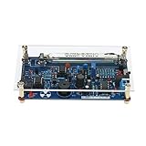
- This kit is compatible with Arduino.
- Made of premium quality materials, it will not rust and is durable.
- Supports most of the Geiger tube: M4011, STS-5, SBM20, J305, etc. (the 330~600V operating voltage of the Geiger tube can be supported).
- Support the computer (PC) data acquisition, Matlab analysis and processing.
- Good kit for MCU software developers that just want to drive Geiger Tube for their own software.
- Initialize: Open the serial or DAQ connection and report a clear error if the device cannot be reached.
- Configure: Set the connection or counter task, input, and acquisition settings used by the selected interface.
- Acquire: Run a receive loop for serial data or read the configured DAQ counter. Preserve raw counts and timestamps rather than recording only a derived rate.
- Calculate: Compute counts per minute from a defined, selectable gate interval. Label the interval and units in the interface; the displayed rate is an event-count rate, not by itself a calibrated dose measurement.
- Visualize and log: Show a live trend and save raw counts with timestamps and configuration metadata, including the selected tube and bias setting.
- Close: Stop acquisition and release the VISA or DAQ resources cleanly when the user exits or an error occurs.
Validate the counter before relying on its readings
The cited project descriptions explain architectures and example configurations, but they do not provide a validated accuracy result for this combined build. Treat counting performance and radiation interpretation as separate validation tasks. Check the low-voltage pulse path, confirm that events increment as intended, and verify the high-voltage regulation against the chosen tube’s requirements before interpreting readings.
- Counts appear too high: Investigate noise or multiple logic transitions from one discharge in the pulse-conditioning and input path.
- Counts appear too low: Check for missed pulses, unsuitable signal levels, or events that merge within the detector or counting chain’s response time.
- Voltage does not regulate as intended: Recheck feedback-divider design, the comparator/regulation path, rectifier, and load against the tube and supply design requirements.
- LabVIEW receives no data: Check whether the selected route is serial or DAQ, then verify its connection, configuration, and supported input/task rather than assuming both interfaces use the same acquisition method.
Because a GM tube cannot distinguish radiation types, a count alone cannot identify whether alpha, beta, gamma, or X-ray radiation caused the events. A quantitative radiation interpretation also requires appropriate calibration and a measurement setup validated for the intended application.
Quick Recap
Product prices and availability are accurate as of the date/time indicated and are subject to change. Any price and availability information displayed on Amazon at the time of purchase will apply.

