
For a buck converter, about 30% peak-to-peak inductor-current ripple at nominal load is a useful first-pass target—not a universal rule. It means the ripple is 30% of the average inductor current: the peak is 15% above average and the valley is 15% below it. The final inductance must also meet the regulator data sheet, worst-case operating conditions, current-limit and thermal requirements, and the converter’s behavior at light load.
What does inductor-current ripple mean?
An inductor stores and releases energy as a switching regulator operates, so its current rises and falls during each switching cycle. Peak-to-peak ripple, written as ΔIL, is the difference between the current’s peak and valley in one cycle. Ripple ratio expresses that difference as a fraction of a stated average current, usually the nominal load current for the 30% recommendation.
Frederik Dostal of Analog Devices describes 30% ripple during nominal-load operation as a recommendation commonly found in regulator data sheets and application notes. In Analog Devices’ 2023 explanation, this is a compromise between the inductor size and the current variation the rest of the circuit must accommodate. It is a starting point: the regulator IC’s own design guidance and the actual application determine whether it is suitable.
How do ripple choices change the design?
The examples below are ripple ratios presented by Analog Devices in 2023. The peak and valley percentages follow from dividing peak-to-peak ripple evenly around average current for a triangular ripple waveform operating in continuous conduction.
The Tool Desk
Outbyte Driver Updater FREEScan for outdated or missing drivers - takes under a minuteDriver Scan →Outbyte PC Repair FREERepair Windows errors before they cause bigger problemsFix Now →#1 Best Overall
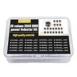
- 20Values each 10pcs,all 200pcs. 1UH - 2.2MH CD43 Wire Wound SMD Power Inductor Assortment Kit, size 4.5mmx4mmx3.2mm
- Including 1UH (1R0),1.5UH (1R5),2.2UH (2R2),3.3UH (3R3),4.7UH (4R7),6.8UH (6R8),10UH (100),15UH (150),22UH (220),33UH (330)
- Including 47UH (470),68UH (680),100UH (101),150UH (151),220UH (221),330UH (331),470UH (471),680UH (681),1MH (102),2.2MH (222)
- Wire Wound SMD Power Inductor Small size, high current resistance, low DC resistance. Lead-free product, RoHS compliant. Carrier tape packaging, suitable for reflow soldering SMT process.
- Wire Wound SMD Power Inductor can be widely used in in buck-boost converters, monitors, notebook computers, network communication equipment, etc.
| Peak-to-peak ripple ratio | Peak and valley relative to average | What the example illustrates |
|---|---|---|
| 7% | Peak 3.5% above average; valley 3.5% below | A much larger inductor and smaller current swing. |
| 30% | Peak 15% above average; valley 15% below | The common first-pass compromise recommended for nominal load. |
| 133% | Peak 66.5% above average; valley 66.5% below | A much smaller inductor and larger current swing. At light load, the valley can reach zero; actual behavior then depends on the converter’s operating mode. |
Lower ripple generally requires more inductance, which can mean a physically larger component. Higher ripple permits less inductance but raises peak current and affects capacitor ripple, losses, and switching-node behavior. The right choice balances those consequences rather than optimizing ripple in isolation.
How do you calculate a first-pass buck inductance?
For an ideal buck converter in continuous-conduction mode, the inductor ripple during the switch-on interval is:
Rank #2

- 25 Values, 242pcs,(6X8mm) Each in Individual compartment with Rated DC Resistance in Ohm, Rated Current in Amp Vertical inductors.
- The coils are made of all-copper conductors, which are used to ensure sufficient inductive capacity and at the same time ensure that they can withstand sufficiently high currents.
- The inductor coil is protected with PVC to ensure stable performance.
- This choke inductor has special guide pin structure; Not easy to produce open circuit phenomenon,Stable electrical performance.
- Include :1uH,2.2uH,3.3uH,4.7uH,6.8uH,10uH,15uH,22uH,33 uH,47uH,68uH,100uH,150uH,220uH,330uH,470uH,680uH,1mH,1.5mH,2.2mH,3.3mH,4.7mH,10mH,20mH,100mH.
ΔIL = (Vin − Vout) × D ÷ (L × fSW)
Equivalently, using the ideal buck relationship D = Vout ÷ Vin:
ΔIL = Vout × (1 − D) ÷ (L × fSW)
Rearrange for the inductance needed for a chosen ripple:
Rank #3

- 20 Values, (6X8mm) Each in Individual compartment with separate door
- 🔴 Rated DC Resistance in Ohm, 🔴 Rated Current in Amp
- Vertical inductors, protected with PVC tube
- (Case 1) 🔵 1uH, 2.2uH, 4.7uH, 6.8uH 10uH, 15uH, 22uH, 33uH, 47uH, 68uH
- (Case 2) 🔵 100uH, 150uH, 20uH, 330uH, 470uH, 680uH 1mH, 2.2mH, 4.7mH, 10mH
L = (Vin − Vout) × D ÷ (ΔIL × fSW)
Here, Vin and Vout are the input and output voltages, D is the duty cycle, L is inductance, and fSW is switching frequency. Choose ΔIL from the chosen ripple ratio multiplied by the stated reference load current. These idealized equations are for a buck converter in continuous conduction; consult the regulator data sheet for its recommended design equation and operating limits. Boost, buck-boost, flyback, coupled-inductor, and multiphase converters require topology-specific analysis.
Calculate the required inductance across the relevant input and output range and identify the operating point that produces the greatest ripple or otherwise constrains the design. Do not assume a nominal calculation covers all conditions: switching frequency, duty cycle, voltage range, component tolerance, and the regulator’s behavior matter. Texas Instruments’ TPS5401 documentation uses a 0.3 ripple-current coefficient and gives a 42 µH minimum-inductance example; that example belongs to its stated design context, not every buck converter.
Rank #4

- 【13 Value CD54 SMD Power Inductors】You will get 130 pieces of CD54 SMD power inductor kit, including 2.2UH 3.3UH 4.7UH 6.8UH 10UH 22UH 33UH 47UH 100UH 220UH 330UH 470UH 41 transparent mesh box. Sufficient quantity for your general needs.
- 【High Quality】The plug-in inductor is made of durable and practical ferrite core, metal material, the quality and meticulous craftsmanship can prevent the inductor from rusting. Each value is produced under strict standards that are precise and conform to their values.
- 【Product Features】The maximum temperature range of the inductor is -55 ℃~+105 ℃; Rated voltage: 16V, 25V, 35V, 50V (varies by model); Capacitor tolerance: ± 20%; Maximum temperature range: -55 ℃~+105 ℃.
- 【Easy to Use】We pack the inductor in a plastic storage box, and put a clearly visible label on the surface of the box. The label corresponds to the inductance of the corresponding size, which is convenient and quick to use.
- 【Wide Application】CD54 wire wound chip power inductor kit can be widely used in buck-boost converters, monitors, computer boards, PCB boards, PCs, laptops, radios, TVs, speakers, copy smart door locks, network communication equipment, etc.
How should you select and verify the inductor?
- Define the converter and operating range. Record topology, input-voltage range, output voltage, load range, switching frequency, and the regulator’s current limit and recommended design method.
- Choose a starting ripple target. About 30% of nominal load current is a common starting point for a buck converter. Follow the IC data sheet if it specifies a different target or method, and state clearly whether your ratio uses nominal or maximum load current.
- Calculate required inductance at constraining conditions. Use the applicable buck equation and evaluate the voltage and switching-frequency conditions that produce the largest ripple or minimum inductance requirement.
- Select a standard value and recalculate. Use the selected inductor’s nominal value, then account for tolerance and DC-bias derating to estimate the inductance available in operation. Recalculate ripple using that value rather than assuming the target was achieved exactly.
- Check peak current and current ratings. In continuous conduction, estimate peak current as average inductor current plus half the peak-to-peak ripple. Confirm adequate margin against the inductor’s saturation-current rating and the controller’s current limit; check the component manufacturer’s rating conditions rather than treating a rating as a universal operating point.
- Check heating and losses. Verify RMS current capability and temperature rise, DCR-related copper loss, and core loss at the actual switching frequency and operating conditions. Consider board copper and airflow as part of thermal performance.
- Check light load and transients. Compare ripple with the actual average inductor current at light load. If the valley approaches or crosses zero, the converter may enter discontinuous conduction or switch to another control mode; use the data sheet’s guidance for that mode. Also check transient response across the load steps the design must support.
- Verify the surrounding circuit and layout. Reassess output-capacitor ripple and switching-node behavior, and review layout because inductor ripple affects output ripple and conducted or radiated EMI behavior.
What should you compare between candidate inductors?
Nominal inductance alone is not enough to establish suitability. Compare each component under the conditions your converter will encounter:
- Inductance tolerance and DC-bias derating: the effective inductance can be lower than its nominal value under current.
- Peak and saturation current: check the manufacturer’s definitions and operating conditions, then preserve margin relative to calculated peak current.
- RMS current and temperature rise: confirm the part can handle continuous heating in the intended PCB and thermal environment.
- DCR and copper loss: lower resistance can reduce conduction loss, though it may affect size, cost, or availability.
- Core loss: assess loss at the switching frequency and ripple relevant to the design.
- Package, shielding, cost, and availability: ensure the physical size and shielding suit the board and EMI needs, and confirm the selected part can be sourced.
- Load and temperature behavior: check that inductance and ratings remain suitable over the converter’s operating range.
Analog Devices names Vishay’s online inductor-selection tool and Coilcraft’s selection and loss tools as resources for comparing parts. Use any tool result as a candidate-selection aid, then confirm its assumptions against the component data sheet and regulator design requirements.
Quick Recap
Best Value

- 🏅【 14 Value CD54 SMD Power Inductor 】:You will get 140Pcs CD54 SMD Power Inductor, including 2.2UH 3.3UH 4.7UH 6.8UH 10UH 22UH 33UH 47UH 68UH 100UH 220UH 330UH 470UH 680UH, which are classified in 14 grid transparent box. Sufficient quantities meet your general needs.
- 🏅【 High Quality 】:The plug-in inductors are made of durable and practical material, quality and meticulous craftsmanship can keep the inductors from rust. Each value is produced under strict standards, which is precise and fits their values.
- 🏅【 Stable Performance 】: CD54 Wire Wound SMD Power Inductor Small size, high current resistance, low DC resistance. Lead-free product, RoHS compliant. Carrier tape packaging, suitable for reflow soldering SMT process. AEC-Q200 qualified product. Working temperature: -40℃~+125℃ (including coil heating)
- 🏅【 Easy to Use 】:We pack the inductors into a 15-grid plastic storage box, and stick a clearly visible label on the surface of the box. The label corresponds to the inductor of the corresponding size, which is convenient and quick to use.
- 🏅【 Widely Applications 】:CD54 Wire Wound SMD Power Inductor can be widely used in in buck-boost converters, monitors, notebook computers, network communication equipment, etc.
Product prices and availability are accurate as of the date/time indicated and are subject to change. Any price and availability information displayed on Amazon at the time of purchase will apply.

