
Some three-phase squirrel-cage induction motors can run from single-phase power using a Steinmetz connection: a permanent AC motor-run capacitor shifts current in one winding to create an artificial third phase. It is not true three-phase conversion. The winding currents are unbalanced, and the motor typically delivers less usable output and starting torque than it does on a proper three-phase supply.
This approach can suit a lightly loaded fan, blower, or pump when reduced performance is acceptable. It is a poor choice when the machine must start under a heavy load, deliver full rated output, or provide predictable performance. Mains wiring, capacitor selection, and protection require a competent installer; a discharge resistor does not make the equipment safe to work on while energized.
When the capacitor method makes sense
A capacitor-based retrofit is most suitable when the motor is relatively small, the load starts easily, and fixed speed is acceptable. Eaton describes Steinmetz output as approximately two-thirds of the motor’s three-phase output; treat that as a practical approximation, not a guaranteed rating for every motor. Eaton also reports that starting torque may be about 30% of rated-load torque without a separate starting capacitor, while direct starting current can be approximately 3–4.5 times rated operating current. Actual results depend on the motor, capacitor, supply, and load. See the Eaton DC1 technical manual.
- Potentially suitable: lightly loaded fans, blowers, and pumps that can accelerate without a substantial load.
- Usually a poor fit: compressors, hoists, loaded conveyors, saws, or other machinery with high breakaway torque; applications needing full motor output, frequent reversing or braking, variable speed, or safety-critical performance.
- Consider the service: a large motor relative to the available single-phase supply may create unacceptable starting current or voltage drop.
If the motor must start under load or deliver dependable torque, compare a single-phase-input VFD, a phase converter, a suitable single-phase replacement motor, or a three-phase utility supply before choosing a capacitor connection.
#1 Best Overall

- BOJACK 35+5uF ±6% 370V/440V CBB65 Dual run circular start capacitor
- Capacitor dimension: Diameter, Height
- Operating temperature: -40 ℃ to +70℃/-104℉to+158℉
- Safety rated: 10,000 AFC
- Three terminals on the top are labeled "Herm"/"H" for the compressor motor, "Fan"/"F" for the fan, and "C" for the common line.
Check the motor before choosing a connection
Start with the motor nameplate and manufacturer’s connection diagram. A common candidate is a three-phase squirrel-cage induction motor with six accessible winding terminals and a dual-voltage rating. A motor marked 230/400 V Δ/Y, for example, is generally connected in delta for 230 V operation, subject to its documentation and condition. Its windings should not be put in a configuration that leaves them at the wrong voltage.
- Confirm the motor type, nameplate voltage, frequency, full-load current, and connection diagram.
- Verify that the winding connection can be configured for the available supply voltage. The lower dual-voltage rating normally corresponds to delta and the higher to wye/star, but follow the motor’s diagram.
- Six accessible winding ends are strongly preferred. A motor with only three external leads cannot normally be reconfigured safely without manufacturer documentation.
- Check for a brake, built-in electronics, unusual winding arrangement, or manufacturer restriction that makes this use unsuitable.
- Confirm that the machine can tolerate reduced output and low starting torque.
Do not identify winding terminals by wire color alone. Use the nameplate, terminal markings, manufacturer documentation, and appropriate electrical tests. If the winding arrangement cannot be established confidently, have a motor shop identify it.
How the Steinmetz connection works
The supply remains single-phase. Two corners of the motor’s delta winding arrangement connect directly across the supply; a run capacitor connects the remaining corner to one supply line. The capacitor shifts current and helps create a rotating field, but the resulting winding currents are not balanced as they would be on a genuine three-phase supply. This unbalance explains the reduced output and the need to measure current and temperature rather than judging the setup by whether the shaft turns.
Rank #2

- BOJACK 7.5 uf MFD 370V/440VAC Oval Run Start Capacitor
- Operating Temperature Range -40 ℃ to +70 ℃/ -104℉ to +158℉
- This Capacitor Will Run Compressor And Fan Motor
- UL Recognized,Engineered For Safety 10 000 AFC Anti Explosion Pressure Switch
- Replacement for :27L566BZ3 , 27L566 , 27L566S , 97F9001 , Z97F9001 ,97F9001BX ,CPT-00120 ,TP-CAP-7.5/440,TOCF7.5
For a conventional six-terminal motor, the basic topology is: connect the two supply lines to two delta corners, then connect the capacitor between one supply line and the third delta corner. Which supply line receives the capacitor connection affects rotation. The exact terminal-to-terminal wiring and reversal method depend on the motor diagram; use it rather than assuming a universal jumper layout. Eaton documents the direction-dependent capacitor connection, and Siemens provides a Steinmetz connection example.
Free tools Windows power users keep installed
One-click scans. No signup required.
Choose delta or wye from the motor diagram
For a dual-voltage motor, the relevant question is whether the motor’s winding voltage matches the available supply in the selected connection. Delta is used when the lower nameplate voltage matches the supply; wye/star is used when the higher nameplate voltage matches it. Thus, a 230/400 V Δ/Y motor is generally configured in delta for 230 V, not in wye. A motor with only a higher delta rating may not suit a lower-voltage supply.
Terminal labels such as U1/U2, V1/V2, and W1/W2 are common, but physical terminal order and jumper placement vary. Do not copy a generic jumper layout without checking the motor’s own diagram. If the available supply does not match an approved winding connection, do not try to compensate with a capacitor.
Rank #3

- six capacitors are produced from a single, continuous, winding
- AmRad Engineering's patented Ultramet capacitor technology
- Item Package Dimension: 5.0" L x 3.0" W x 3.0" H
- Country Of Origin: United States
Estimate the run-capacitor size
For 230 V operation, a common initial estimate is about 60–80 µF per kW. Eaton gives approximately 70 µF/kW in its technical documentation, while noting that the correct value depends on voltage and connection. This is a starting point for evaluation, not a universal sizing formula.
Example: for a 1.5 kW motor, the 70 µF/kW estimate gives 1.5 × 70 = about 105 µF. Choose an appropriate motor-run capacitor near that value only after confirming actual winding currents and motor temperature under the intended load.
- Too little capacitance can lead to weak starting, poor load performance, and excessive current in a directly supplied winding.
- Too much capacitance can over-excite the auxiliary winding, raise current and heat, and damage the motor.
- The suitable value varies with motor design, voltage, frequency, connection, load, and desired operating point.
Do not substitute a formula that uses a different voltage, frequency, horsepower or power-unit convention without verifying the convention and assumptions. Measure current in each accessible motor lead and check temperature at the intended load; a motor that spins can still have a winding overheating.
Rank #4

- BOJACK 45+5uF ±6% 370V/440V CBB65B Dual run circular start capacitor
- Capacitor dimension: Diameter(65 mm/2.56 inch) Height(95 mm/3.74 inch)
- Operating temperature: -40 ℃ to +70℃/-104℉to+158℉ ,Safety rated: 10,000 AFC
- Three terminals on the top are labeled "Herm"/"H" for the compressor motor, "Fan"/"F" for the fan, and "C" for the common line.
- Replacement for 97F9895 , Z97F995 , 97F9895BZ3 , 27L880 , TRCD455 , TRCFD455 , PRCFD455 , 27L889 , 97F9851 , 97F9851S , 12788 , RC0114 , Z97F9895 , 97F9895 , TT-CAP-45/5/440R , HC98KA046 , TP-CAP-45/5/440R , CAP050450440RT , HC98JA046 , HCKS450D050R440Z , 00662441180262
Select a motor-run capacitor
Use a continuous-duty AC motor-run capacitor, not an ordinary polarized electrolytic capacitor. IEC 60252-1 covers capacitors used with asynchronous motors supplied from a single-phase system, including capacitors that enable three-phase motors to operate from single-phase supplies. See the IEC 60252-1 scope and the TDK motor-run and motor-start capacitor catalog.
- Choose a part approved for motor use and rated for continuous duty under the applicable standard, such as IEC 60252-1 or UL 810 where relevant.
- Its AC voltage rating must suit the supply and the voltage stress in the phase-shift circuit. A 400/450 VAC motor-run capacitor is commonly selected for 230/240 V installations, but confirm the motor and capacitor manufacturers’ requirements.
- Check temperature range, safety class, terminal style, physical mounting, and enclosure suitability—not just the capacitance value.
- Do not leave a motor-start capacitor permanently connected unless that exact component is explicitly designed and rated for continuous duty.
Use a starting capacitor only with suitable switching
A run capacitor alone may not start a motor against its load. A larger temporary starting capacitor connected in parallel with the run capacitor can increase starting torque, but it must be disconnected after acceleration by an appropriate relay, centrifugal switch, timer, or purpose-designed control. Eaton describes a possible increase toward approximately 90–100% of rated-load torque with a correctly designed starting-capacitor arrangement; that is not a guaranteed result for every motor or load. Its DS7 manual discusses the arrangement.
- Select a start capacitor rated for its intended duty and switching frequency.
- Do not leave it connected during normal running. A failed switch or control can destroy the capacitor or motor.
- Do not assume a start capacitor is interchangeable with a run capacitor. IEC treats these separately: IEC 60252-2 covers motor-start capacitors.
- Do not hand-start exposed machinery to overcome inadequate starting torque.
Calculate a capacitor discharge resistor
A resistor connected across a capacitor can reduce retained voltage after disconnection. For an ideal capacitor discharging through a resistor, use:
Best Value
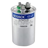
- BOJACK 40+5uF ±6% 370V/440V CBB65 Dual run circular start capacitor
- Capacitor dimension: Diameter Height
- Operating temperature: -40 ℃ to +70℃/-104℉to+158℉
- Safety rated: 10,000 AFC
- Three terminals on the top are labeled "Herm"/"H" for the compressor motor, "Fan"/"F" for the fan, and "C" for the common line.
V(t) = V0e−t/(RC)
Rearrange for resistance:
R = t / [C ln(V0/Vt)]
- R is resistance in ohms; C is capacitance in farads.
- t is the desired discharge time in seconds.
- V0 is the initial capacitor voltage and Vt is the target residual voltage.
For an illustrative 40 µF capacitor, treating the initial voltage as 230 V and targeting 50 V or less after 60 seconds gives R = 60 / [0.000040 × ln(230/50)] = approximately 800 kΩ. This is an estimate based on those assumptions, not a universal resistor value. The phase-shift circuit can subject a capacitor to a voltage different from the nominal supply; confirm actual operating and discharge conditions against component documentation. A commonly cited IEC-based target is 50 V or less within 60 seconds. KEMET’s motor-start capacitor datasheet gives an IEC-based approximation of R (kΩ) = T/C (µF); at approximately 220 V, its stated T value of 32,000 yields 800 kΩ for 40 µF.
Check resistor rating, placement, and whether one is already fitted
Estimate continuous dissipation using P = VRMS2/R. At 230 V and 800 kΩ, this is about 0.066 W. That theoretical dissipation is not by itself a sufficient component specification: allow for mains tolerance, temperature, repetitive switching, actual capacitor voltage, resistor working-voltage limits, and installation creepage and clearance. Select a suitably rated component and install it so it cannot short the capacitor or expose people to live terminals.
Some capacitors include an internal discharge resistor or other safety feature. Check the part marking and datasheet before adding one; TDK and Iskra document capacitor families and installation information at their capacitor catalog and motor capacitor documentation. A discharge device may not be required in every installation, depending on the capacitor’s permanent connection, accessibility, product design, and applicable rules. Treat an accessible capacitor as charged until verified otherwise. For service, isolate and lock out the supply, wait as specified, and verify voltage with a properly rated meter; never use a resistor as a substitute for safe isolation.
Provide suitable protection and controls
This is mains-voltage equipment. The installation must meet local electrical rules and the motor and control manufacturers’ requirements. At minimum, the design needs a lockable disconnect, correct branch-circuit protection, grounding and bonding, enclosed motor terminals and capacitor, and motor overload protection selected for the actual setup. Use a contactor rated for the single-phase load.
Do these 3 things before closing this tab:
1Scan for outdated or missing drivers - takes under a minute2Clear out junk files and repair common Windows errors3Fix the driver behind crashes, sound loss and screen glitchesDo not assume a three-pole starter or overload relay will sense current correctly when used on single-phase power. Some devices require current to pass through all three sensing paths or a manufacturer-specific configuration. Follow the device instructions rather than bypassing an overload or routing the load through two poles by guesswork. See Schneider Electric’s guidance on three-phase starters in single-phase applications.
Independent reader supportYour contribution helps us test, update, and keep practical guides available for everyone.Commission and verify the installation
- Confirm nameplate voltage, frequency, current, connection diagram, and required rotation. Verify that the windings can be connected for the supply voltage.
- Inspect bearings, shaft, coupling, driven load, and any brake. Disconnect the load for initial testing where practical.
- Install the run capacitor, disconnect, protective devices, grounding, enclosure, and any properly designed discharge resistor. Verify wiring with the supply isolated.
- Have a competent person energize the motor briefly and check direction. Isolate before changing wiring; follow the motor diagram to reverse it.
- Measure current in each accessible motor lead under no-load and working-load conditions. Compare readings with motor limits and the protection device’s instructions.
- Run at the intended load while monitoring motor temperature, acceleration, vibration, sound, and capacitor condition.
- Stop if current exceeds the applicable limits, acceleration is poor, the motor hums or stalls, or abnormal heat, vibration, or noise appears. Correct the cause rather than increasing capacitance blindly.
- After shutdown, verify capacitor discharge behavior with a properly rated meter. The resistor is not a maintenance isolation procedure.
Troubleshoot common symptoms
| Symptom | Possible causes | Corrective direction |
|---|---|---|
| Hums but does not start | Insufficient starting torque, excessive load, incorrect delta wiring, open winding, or a faulty capacitor. | Isolate power; verify the winding connection and capacitor, and test unloaded where practical. Reconsider the starting method or choose another solution. |
| Starts only when spun by hand | Insufficient starting torque or an unsuitable rotation connection. | Do not hand-start exposed machinery. Use a properly switched starting arrangement if appropriate, or consider a VFD or motor replacement. |
| Runs hot at no load | Excessive capacitance, incorrect connection, voltage mismatch, or winding-current imbalance. | Stop and verify the nameplate connection and measured currents. Reassess capacitance based on measurements. |
| Trips overload under load | Load exceeds available output, current imbalance, or incorrect overload sensing. | Reduce load, measure current in each lead, and verify overload-device configuration. Consider a VFD or different motor solution. |
| Capacitor bulges, vents, or fails | Wrong capacitor duty or voltage rating, excessive voltage or capacitance, overheating, or a start capacitor left connected. | Isolate the equipment and replace the failed part only after correcting the cause and confirming the proper component and switching. |
| Rotation is reversed | Capacitor connected to the opposite supply side for the chosen direction. | Isolate and follow the motor terminal diagram for the correct capacitor connection. |
| Speed falls sharply under load | Load exceeds available torque, capacitor choice is unsuitable, or supply voltage drops. | Reduce load and check supply voltage and current. Consider a VFD or replacement motor if performance is inadequate. |
| Voltage remains after shutdown | Missing or failed discharge path, dielectric absorption, or incorrect resistor installation. | Keep isolated, verify voltage, and use an approved discharge and service procedure. Repair the discharge path before returning the equipment to service. |
| Overload relay does not trip as expected | Current is not passing through all sensing poles or the relay is not configured for single-phase use. | Follow the starter manufacturer’s single-phase instructions; do not bypass protection. |
Compare the alternatives
| Option | Best suited to | Main trade-offs |
|---|---|---|
| Steinmetz capacitor connection | A fixed-speed motor with a light load where reduced output and starting torque are acceptable. | Simple relative to other options, but winding currents are unbalanced, output is reduced, and capacitor selection and thermal checks are motor-specific. |
| Single-phase-input VFD | Applications needing controlled acceleration, speed control, or improved starting performance, when the motor and drive are suitable. | More capable but more complex and costly. The drive must specifically permit single-phase input; some models require oversizing and a line reactor. See Schneider Electric’s single-phase-input guidance. Do not connect existing motor capacitors to a VFD output unless the manufacturer explicitly approves it; Eaton warns of damaging voltage and current peaks in its VFD application note. |
| Rotary or electronic phase converter | A workshop with multiple three-phase loads or an installation where a converter is justified. | Requires suitable converter equipment and engineered loading; rotary units also need an idler motor and can add noise and maintenance. |
| Purpose-built single-phase motor | A fixed installation where predictable single-phase performance and starting behavior matter and a mechanically compatible motor is available. | Requires a suitable mounting, shaft, and performance match. |
| Three-phase utility service | A large, heavily loaded, or continuously operated motor for which a capacitor retrofit would be a poor compromise. | May require service changes, but avoids forcing a motor to operate with the capacitor method’s imbalance and reduced output. |
A VFD is not automatically the right purchase: it must accept single-phase input and suit the motor and installation. Conversely, a capacitor is not a shortcut to full three-phase performance. Choose based on starting torque, required output, speed control, duty cycle, supply capacity, and installation requirements.
Quick Recap
Product prices and availability are accurate as of the date/time indicated and are subject to change. Any price and availability information displayed on Amazon at the time of purchase will apply.

