
The branch current method finds current in a DC network by treating each branch current as an unknown, then applying Kirchhoff’s Current Law (KCL), Kirchhoff’s Voltage Law (KVL) and Ohm’s law. Choose a direction for every unknown current, write enough independent equations to solve them, and interpret any negative answer as current flowing opposite to its assumed arrow.
What the branch current method does
A branch is a path between two nodes in a circuit; it may contain one component or several components in series. In this method, the unknowns are the currents in the branches. KCL supplies current-balance equations at nodes, while KVL supplies voltage-balance equations around independent loops. Ohm’s law connects the voltage across a resistor to its current.
The method is especially direct when the goal is to find branch currents. It converts the circuit into simultaneous equations, which you solve together rather than trying to infer each current separately.
Set up the circuit and choose current directions
- Mark the nodes and branches. Identify the junctions and the distinct paths between them. Label each branch current, such as I1, I2 and I3.
- Draw a reference arrow for every unknown current. Choose convenient directions; the arrows are assumptions for setting up the equations, not claims about the eventual flow.
- Label component values and polarities. For each resistor, relate voltage and current with Ohm’s law, V = IR. Keep resistor polarity consistent with the assumed current direction: under the passive sign convention, the current enters the resistor’s positive terminal.
- Choose a consistent sign convention. For KCL, for example, count currents entering a node as positive and currents leaving as negative. For KVL, select a loop traversal direction and consistently record voltage rises and drops.
It is fine to choose a different sign convention, but do not switch conventions midway through an equation set.
#1 Best Overall
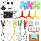
- COMPLETE CIRCUIT KIT: Comes with one instructions, 5 x crocodile clip leads, 5 x bulbs, 2 x motors, 2 x motor holder, 2 x rocker switches, 3 x propeller with 3 Vanes, 3 x propeller with 4 Vanes, 1 x buzzer sounder, 1 x bulb holders, AA size battery holder (1 x 1.5V), AA size battery holder (2 x 1.5V), packaged with enough circuit accessories for you do science project easily
- SCIENCE EXPERIMENT KIT: This popular and interesting electronic science experiment STEM toys can well inspire and encourage kids learning about science. This Montessori learning toy is good for curious kids, turning your own new ideas and inventions into reality. Also perfect for Children's school science STEM engineering projects, Ideal back to school gift for curious minds
- WIDE APPLICATIONS: The circuit motor kit can well catch kids attention and let the them try to build, experiment and explore basic electrical simple circuits. It can also be used in school in science, STEM, technology and design courses, easy to meet your project needs, properly educating some circuit knowledge would be a good interaction time with your kids together
- NOTICE: It is recommended that the voltage be 1.5V-3V. If the voltage is 3V, please control the time. The use time should not be too long, and the time should be controlled within 3 minutes. After 5-10 minutes, the circuit will generate heat and a short circuit.
- WARNING: Suitable for 8+ years. CHOKING HAZARD—Small parts, not for children under 3 years. Be careful of scald caused by short circuit. Do not mix old and new batteries. Do not mix alkaline, standard (carbon-zinc), or rechargeable batteries, the kids must use under the supervision of adults
Write the KCL and KVL equations
Apply KCL at the needed nodes
KCL says the algebraic sum of currents at a node is zero: current entering equals current leaving. At a node where I1 enters and I2 and I3 leave, one valid equation is I1 − I2 − I3 = 0. The signs follow the chosen convention and the arrows on your circuit.
In a connected circuit, not every node equation is independent: the sum of all node equations duplicates the same current balance. Use independent equations rather than adding redundant ones.
Rank #2

- Complete Circuit Kit : Comes with one Introduction, 4 pieces wires, 3 pieces bulbs, bulb holder, AA size battery holder, motor, switch, buzzer Sounder, propeller fan, packaged with complete circuits accessories for you do science project easily.
- Electric Motor Kit : This Popular And Interesting Electronic Science Kit Can Well Inspire And Encourage Kids Learning About Science. This Learning Toy Is Good For Curious Kids, Turning Your Own New Ideas And Inventions Into Reality. Also Perfect For Children's School Science Stem Toys Projects.
- Wide Applications: The circuit electric dc motor kit can be used in school in science, STEM, technology and design courses, easy to meet your project needs, develop your learning skills and hand-on ability.
- Features: This science kit is the ideal fun educational gift for kids and teenage who like STEM and science projects. The circuit kit can inspire kids curiosity and creativity, well learn simple principles. The circuit has multiple paths, each circuit is independent of each other, one circuit component is open, and the other branches work as usual.
- Pay Attention: The circuit board for kids suitable for 8+ years, please read the circuit kit pictures carefully, use the correct circuit to avoid short circuit, short circuit will produce high temperature and cause the battery holder case to melt and burned, the kids must use under the supervision of adults.
Apply KVL around independent loops
KVL says the algebraic sum of voltage changes around a closed loop is zero. Trace each loop in one direction, recording a rise or drop as you cross each source and component. Replace resistor voltages with IR, using the current reference direction and resistor polarity marked in the setup.
For a resistor traversed in the direction of its assumed current, the traversal is a voltage drop of IR; traversing it in the opposite direction is a rise of IR. Apply the same careful polarity accounting to voltage sources. Select enough independent loops to provide the equations needed alongside KCL.
Rank #3

- Complete Circuit Kit: Comes with one Introduction, 4 pieces crocodile clip leads, 3 pieces bulbs, bulb holder, AA size battery holder, motor, rocker switch, propeller fan, packaged with complete circuit accessories for you do science project easily
- Electronic Science Toys: This popular and interesting electronic science kit can well inspire and encourage kids learning about science. This Montessori learning toy is good for curious kids, turning your own new ideas and inventions into reality. Also perfect for Children's school science STEM toys projects
- Notice: It is recommended that the voltage be 1.5V-3V. If the voltage is 3V, the use time should not be too long, and the time should be controlled within 3 minutes. After 5-10 minutes, the circuit will generate heat and short circuit.
- Wide Applications: The electric circuit motor kit includes familiar components can be used in school in science, STEM, technology and design courses, easy to meet your project needs, develop your learning skills and hand-on ability
- Pay Attention: Suitable for 8+ years, please read the circuit pictures carefully, use the correct circuit diagram to avoid short circuit, short circuit will produce high temperature and cause the battery holder case to melt and burned, the kids must use under the supervision of adults
Solve the simultaneous equations and read the signs
Combine the independent KCL and KVL relations, then solve for the unknown branch currents using algebra or a linear-equation solver. The solution’s sign tells you how the actual current relates to the arrow you initially chose:
- Positive current: the current flows in the assumed arrow direction.
- Negative current: the current’s magnitude is the absolute value of the answer, and it flows opposite to the assumed arrow.
A negative current is not, by itself, a mistake. It indicates that the initial reference direction was opposite to the solved direction.
Rank #4

- It is a safe introductory kit for electricity. It helps student to consolidate the knowledge in textbooks and gain a deeper understanding of the basics of current. The Basic Electricity circuit kit can build various kinds of the series and parallel circuits like the basic circuits in the English manual.
- This kit contains English instructions, which makes it easier for you to assemble series and parallel circuits. By setting up simple circuits, it is easier for student to learn basic electrical rules and improve theirs hands-on ability, thinking ability, creativity, and improvement. Awareness of electricity.
- This Kit is ideal for 7rd~9th grade science project,summer camps, science fairs, hands-on center,science clubs , home school unit study,Teaching Aids,and generally for anything related to the STEM education.
- All accessories are packed in a plastic storage box. When you are not using it, you can put it in the box and store it. Note: This set does not contain two AA batteries.
- Please feel free to contact us if you have new ideas for EUDAX Product, we will provide Best After-sales service
A textbook example—and what its numbers mean
A three-branch textbook example reports I1 = 2 A, I2 = 1 A and I3 = 1 A after solving its simultaneous equations. Those values belong to that example’s particular circuit; they are not standard currents or a result of the branch-current method in general. The excerpt’s edition and publication year are not established in the available listing.
Check the answer and avoid common setup errors
- Substitute into KCL. At each node used in the analysis, confirm that entering and leaving currents balance under your convention.
- Substitute into KVL. Check that the algebraic voltage changes sum to zero around each loop you used.
- Recheck signs and polarities. A mismatch between an assumed current arrow, resistor polarity, loop traversal direction or source polarity can reverse a term in an equation.
- Report negative answers clearly. State the magnitude and actual direction relative to the circuit, rather than treating the minus sign as a failed calculation.
When to use branch-current, mesh-current or node-voltage analysis
Branch-current analysis is a straightforward choice when the requested results are the currents in individual branches. Its main trade-off is equation count: a larger network can require more simultaneous equations than mesh-current or node-voltage analysis. The more systematic alternatives may therefore be more efficient, depending on the circuit.
PC Slower Than It Used to Be?
A free scan shows the junk files, broken settings and background clutter dragging Windows down - then fixes them in one click.Free scan · Windows 10 & 11Outdated Drivers Are Slowing You Down
One free scan finds every outdated or missing driver and matches the right update for your exact hardware.Free scan · exact hardware matchBest Value

- Working Input Voltage: DC4.5V; PCB Size:70×51mm; High-quality FR4 fiberglass circuit board with clear component marking, reinforced tinned solder pads, anti-oxidation & durable for repeated soldering; Package includes bare PCB, full discrete electronic components, miniature DC motor and 3-blade yellow plastic fan; NOTE: Items are loose unfinished components, customers need to complete soldering and assembly by themselves with included installation instruction.
- Core circuit based on classic NE555 timer IC; R1/R2/C1 together with 50K adjustable potentiometer W1 constitute adjustable pulse width oscillation circuit; Rotate variable resistor to change output pulse frequency and duty cycle, realize stepless smooth speed regulation for DC motor and cooling fan.
- Multiple protection & filter circuits pre-designed on PCB: D1 reverse polarity protection diode prevents chip burnout from wrong power connection; D3 + C5 absorb back EMF generated by DC motor to protect driving triode; C2/C4 for power supply filtering, C3 stabilizes reference voltage to eliminate circuit clutter interference.
- Standard textbook-level NE555 PWM application circuit, core teaching accessory for middle school and college analog electronics courses; Help students intuitively learn pulse oscillation principle, PWM duty cycle control, transistor switching characteristics and DC motor driving theory.
- Ideal for student electronic competition soldering drills, classroom hands-on experiment and after-school STEM handmade activity; After full assembly, finished adjustable speed fan can be used as small DIY cooling fan, model car motor speed test module.
| Method | Unknowns to solve for | Useful consideration |
|---|---|---|
| Branch-current | Branch currents | Directly targets branch currents, but can produce a larger equation set in a complex network. |
| Mesh-current | Mesh currents | Named as an alternative that may reduce equation count; its fit depends on circuit topology. |
| Node-voltage | Node voltages | Named as an alternative that may reduce equation count; it targets node voltages rather than branch currents directly. |
These are choices, not a universal ranking. Consider how many unknowns each method would create for your circuit, whether the topology lends itself naturally to mesh analysis, and whether you need branch currents or node voltages as the final answer.
Quick Recap
Further reading
- All About Circuits: Branch Current Method Analysis | DC Network Analysis explains the KCL/KVL setup, sign interpretation and equation-count trade-off.
- Lessons In Electric Circuits — Volume I (DC), Chapter 10 presents the method in an open educational text.
Product prices and availability are accurate as of the date/time indicated and are subject to change. Any price and availability information displayed on Amazon at the time of purchase will apply.

