
iTechGuides is reader-supported. When you buy through links on our site, we may earn an affiliate commission. As an Amazon Associate I earn from qualifying purchases. Learn more
A reed relay is an electrically controlled switch: current through a coil creates a magnetic field that moves two small metal reeds together inside a sealed glass capsule, closing the circuit. When the coil is de-energized, the reeds spring apart. Its sealed, low-mass contacts make it useful for isolated, low-level signal switching, but the exact relay’s load ratings and operating conditions still determine what it can safely switch.
How a reed relay works
A dry reed relay contains two overlapping ferromagnetic blades, called reeds, inside a hermetically sealed glass capsule. The capsule may be evacuated or filled with protective gas. The reeds serve as both the electrical contacts and the moving magnetic parts of the switch.
When current flows through the relay coil, its magnetic field pulls the reeds together and completes the circuit. When coil current stops, the reeds’ spring force separates them. The coil and switched contacts are electrically isolated from each other, a property known as galvanic isolation.
Do these 3 things before closing this tab:
1Scan for outdated or missing drivers - takes under a minute2Repair Windows errors before they cause bigger problems3Fix the driver behind crashes, sound loss and screen glitchesBecause the contacts are smaller and lighter than those in many conventional electromechanical relays, they can move quickly. National Instruments says a reed relay can switch about ten times faster than an electromechanical relay with equivalent ratings; actual performance depends on the specific parts and operating conditions. National Instruments’ reed relay overview describes the contact construction and comparison.
#1 Best Overall

- Model: SIP-1A05
- Origin: Chinese Mainland
- Power supply mode: DC 5V
- DC resistance: 450~550ohm
- Voltage: ≤ 36V
What makes reed relays different from regular relays?
“Regular relay” can refer to several electromechanical designs. A reed relay is one type of electromechanical relay, distinguished by its sealed reed contacts and magnetic actuation. Larger general-purpose relays often use exposed or enclosed conventional contact mechanisms, which can have greater moving mass. The design choice matters more than the label: compare the exact contact ratings, speed, isolation, lifetime, and package for the application.
| Characteristic | Reed relay | Solid-state switch |
|---|---|---|
| Switching mechanism | Mechanical reeds pulled together by a coil’s magnetic field | Electronic components; no moving contacts |
| Isolation and signal behavior | Provides galvanic isolation; can suit low-level signals and bidirectional switching, subject to model ratings | Depends on device type; may have leakage, on-resistance, or directionality tradeoffs |
| Wear and noise | Contacts have finite mechanical life and may produce bounce and switching noise | No contact wear or mechanical bounce, but other electrical tradeoffs apply |
| Drive and speed considerations | Coil consumes power and is an inductive load; switching can be fast for a mechanical relay | May be preferable when silent operation, no contact wear, or very high switching speed is the priority |
Analog Devices discusses these tradeoffs between relays and solid-state switches, including isolation, noise, bounce, efficiency, size, speed, and reliability, in its switches in low-voltage applications article.
Rank #2

- Package: 3 sets of black magnetic door contact reed switches + 6 pieces stickers + 12 pieces screws.
- Size (approx. ): 29 x 15 x 9 mm; cable length: 30 cm.
- It can control DC 3V, 5V, 9V, 12V, 24V, 36V, 48V, Maximum switching voltage: 100V; Maximum switch current: 0.5 amps, maximum switch power: 10W.
- NC&NO Combined, Use Normally Open or Normally Closed freely. Cable definition: Blue for common; Black for NC; White for NO.
- Application Magnetic door contact reed switch, ideal for door alarm sensors, alarms, LED switches, relays, GPS low voltage devices, etc., effective for theft deterrent. Yes, ideal for wooden doors or windows.
Why use a reed relay—and what are its limits?
Benefits
- Clean contacts: Hermetic sealing helps protect the contacts from atmospheric contamination and corrosion.
- Isolation: The coil’s control circuit is separated electrically from the switched circuit.
- Fast signal switching: Low-mass contacts can switch quickly compared with many conventional electromechanical relays.
- Measurement suitability: Some designs support low-level, low-leakage, or high-isolation measurement tasks and compact test matrices.
Tradeoffs
- Finite mechanical life: Contacts can wear, bounce, and generate switching noise.
- Coil-drive requirements: The coil consumes power and behaves as an inductive load. Depending on the circuit, the driver may need a flyback diode or another suitable suppression component.
- Limited contact ratings: Voltage, current, and power limits vary by exact model. Switching conditions and load type also matter; do not infer a safe load from the relay’s name or package.
- Magnetic crosstalk: Nearby relays can influence one another in dense arrays. A shielded version or a different layout may be needed.
Are reed relays normally open or normally closed?
They are available in different contact forms. A normally open relay closes its contact when energized; a normally closed relay opens it when energized. Changeover designs switch a common terminal between two contacts. Check the manufacturer’s contact-form notation rather than assuming all reed relays behave alike.
| Contact form | Common description | Typical notation |
|---|---|---|
| Normally open | One contact closes when the coil is energized | 1 Form A or 1A |
| Normally closed | One contact opens when the coil is energized | 1 Form B or 1B |
| Changeover | A common contact switches between two paths | 1 Form C or 1C; often described as SPDT |
| Two normally open contacts | Two independent normally open contact paths | 2 Form A or 2A |
What can a reed relay switch?
Reed relays are used in applications that need small, isolated switching contacts, including semiconductor automated test equipment, in-circuit PCB test matrices, electrometer and leak-detector inputs, hipot and safety testers, and measurement-instrument signal paths. Application resources from SHR AUTOSENSOR also identify EV high-voltage insulation monitoring, photovoltaic inverter ground-insulation tests, medical equipment such as defibrillators and electrosurgical systems, battery-powered instruments, oscilloscopes, and robotics.
Rank #3
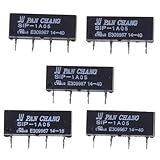
- SPECIFICATIONS: 5V DC reed relay switch module with 450-550 ohm DC resistance, rated for 1A current, featuring normally open (NO) contact configuration
- PACKAGE CONTENTS: Set of 5 black SIP-1A05 relay switches, each with 4-pin configuration for versatile circuit integration
- COMPACT DESIGN: Space-efficient SIP (Single In-line Package) form factor makes these relays ideal for PCB mounting and electronic assemblies
- SWITCHING CAPABILITY: Reliable switching performance with normally open contacts, perfect for low-power signal switching applications
- INSTALLATION: Standard 4-pin configuration enables straightforward integration into existing circuits and control systems
“High voltage” or “low current” alone does not establish that a relay is suitable. Confirm the specific model’s switching voltage, current, power, insulation, and load-type limits. Ratings can differ between resistive, capacitive, and inductive loads, and between switching a load while energized and switching it under other conditions.
How to choose a reed relay
- Set the coil requirements. Choose the nominal coil voltage—common options include 5 V, 12 V, and 24 V DC—and verify coil resistance and allowable power. Confirm that the control circuit can supply the required current. Select a suitable driver and suppression component for the circuit.
- Choose the contact form. Decide whether the circuit needs normally open (1 Form A), normally closed (1 Form B), changeover (1 Form C), or two normally open contacts (2 Form A).
- Match the switched load. Check the exact part’s switching voltage, current, and power ratings. Account for whether the load is resistive, capacitive, or inductive and whether switching occurs while the load is active.
- Check signal-integrity needs. For sensitive measurements, compare contact resistance, leakage, insulation resistance, dielectric withstand, RF performance, and thermal EMF where the manufacturer specifies them.
- Verify the package and assembly constraints. Common package styles include SIP, DIP, surface-mount, and miniature vertical formats. Check the footprint, pinout, dimensions, magnetic shielding, and any cleaning or reflow constraints in the datasheet.
- Check operating conditions and lifetime. Confirm temperature, vibration, shock, and expected switching cycles. If the application needs a relay that retains its state without continuous coil power, verify whether a suitable latching design is available.
Choosing a 5 V reed relay for a prototype
A search phrase such as “5 V SIP normally-open reed relay” narrows the options by coil voltage, package, and contact form. SHR lists SIP-1A05 and SIP-1A05B as 5 VDC models with 1 Form A options. Its standard and miniature product guide lists 5 V, 12 V, and 24 V DC coil options and contact forms 1A, 1B, 1C, and 2A. The same guide gives representative SIP-family switching figures of 200 V DC and 10 W; those are family examples, not guaranteed ratings for every model. Confirm the exact part number’s datasheet before purchase or use.
Rank #4

- ✪Length of glass: 14 mm;Diameter of glass: 2 mm
- ✪Maximum contact resistance: 100M;Minimum Insulation Resistance: 1010
- ✪Package included:6 X Reed Switch+6 X Magnetic chip
- Suitable for industrial control equipment circuits for controlling electromagnetic starters, contactors, relays and other circuits (there are only boxes in here, button switches are not included). Good for electronic projects, power supply units, amplifiers, etc. Suitable for emergency stop rotary switch.
- Dimension:65mm*65mm*75mm
For a marketplace listing, compare the manufacturer part number and datasheet with the listing. Verify coil voltage, contact form, contact ratings, pinout, package dimensions, and seller authenticity; a matching title or photograph is not enough to establish compatibility.
Quick Recap
Best Value

- AC/DC: 10-30 Vac/dc
- AC: 120-277Vac
- Relays: 1 SPST
- Resistive: 10 A
- Motor: 1/3 HP
Before connecting one to a circuit
- Check the exact model’s datasheet, not just a family guide or product listing.
- Ensure the coil voltage, current, and power suit the driver.
- Keep the switched load within its specified voltage, current, and power limits for the actual load type and switching conditions.
- Allow for contact bounce, finite life, and possible magnetic interaction with nearby relays.
- Use an appropriate coil suppression method when required by the driver circuit.
Product prices and availability are accurate as of the date/time indicated and are subject to change. Any price and availability information displayed on Amazon at the time of purchase will apply.

