
Do these 3 things before closing this tab:
1Clear out junk files and repair common Windows errors2Fix the driver behind crashes, sound loss and screen glitches3Repair Windows errors before they cause bigger problemsiTechGuides is reader-supported. When you buy through links on our site, we may earn an affiliate commission. As an Amazon Associate I earn from qualifying purchases. Learn more
The NE555 in this design is not the audio preamplifier: it generates a switching waveform for a converter that supplies high voltage to the tube stages. The documented portable project pairs two 12AX7 tubes with an NE555-based supply, a TDA-series driver and transformer, and an eight-AA battery pack. Its author reports a regulated tube supply of about 80 V and roughly two to four hours of operation, figures specific to that build rather than guaranteed specifications. Project description
What “Tube Preamp – NE555” means
The phrase can mean a tube audio preamp whose high-voltage supply uses an NE555, a project schematic that happens to include a 555, or—incorrectly—a preamp in which the NE555 amplifies the audio. The documented portable design fits the first two meanings. Its 12AX7 stages process the audio; the NE555 is part of the power converter.

The project was published as “Portable Tube Preamp” in Audio Express in March 2010. Publication record and AudioXpress project explanation describe the portable supply and its 555-generated waveform. The project author’s page gives the component and operating details cited below.
What’s actually slowing this PC down?
Pick the symptom - the matching free tool is one click away.
How the project is arranged
There are three related but distinct parts: the audio signal path, the tube heater supply, and the higher-voltage plate supply. A working B+ converter does not by itself provide the correct heater power.
#1 Best Overall
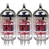
- This tube has a well balanced, colorful tone with strongly defined lows, mids and smooth highs
- It allows for more clean head-room than higher gain 12AX7s
- In overdrive, it is smooth and strong with well defined lows and mids
- When pushed into overdrive it offers clean distortion with well balanced lows and mids
- The JJ 12AX7 is well suited for all types of music and playing styles
Audio path
Audio input → input coupling / gain control → 12AX7 gain stage
            → interstage coupling / level control → second tube gain stage
            → output coupling capacitor → audio output
The project uses two 12AX7 tubes for two audio channels, with adjustable pre- and post-gain functions, according to the project description.
Plate-supply path
Battery pack → NE555 oscillator → TDA-series 2 W driver
             → step-up transformer → rectifier → filter capacitors
             → Zener regulation → tube B+ rail
The documented circuit includes a TDA-series 2 W audio amplifier to drive an old military-surplus audio transformer; it is not simply an NE555 connected directly to a transformer. The project description reports Zener regulation and approximately 80 V for the tube supply.
Heater supply
Plan the heater wiring and its supply separately from B+. Consult the exact tube data sheet and design for the intended heater voltage and current, series or parallel connection, heater-to-cathode insulation rating, and hum-control method. The 12AX7/ECC83 data-sheet index is available at Frank’s Electron Tube Data Sheets; verify the particular tube’s specifications rather than assuming a generic pinout covers every setup.
The Tool Desk
Outbyte Driver Updater FREEScan for outdated or missing drivers - takes under a minuteDriver Scan →Outbyte PC Repair FREEClear out junk files and repair common Windows errorsFree Scan →What the NE555 does in the converter
In astable operation, a 555 repeatedly charges and discharges a timing capacitor, producing a periodic output. TI describes the NE555 as a timer with trigger and threshold levels nominally near one-third and two-thirds of its supply voltage. The standard NE555 datasheet gives electrical characteristics over approximately 5–15 V supply conditions; check the exact manufacturer, suffix, package, and operating conditions before designing around a part. TI NE555 datasheet
Rank #2
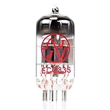
- JJ Tubes are some of the most reliable and popluar vaccum tubes available
- HG+ rated tube, a tested tube great for V1 spot in your amp
- We test every preamp tube for noise, microphonics, gain, and triode balance.
- Tested by trusted industry experts
- 6 Month Warranty Included On All RUBY Tubes
A common first-order astable estimate is:
f ≈ 1.44 / ((RA + 2RB)C)
tH ≈ 0.693(RA + RB)C; tL ≈ 0.693RBC
D ≈ (RA + RB) / (RA + 2RB)
These are approximations for the basic timing arrangement, not a recipe for this preamp. Choose switching frequency and duty cycle with the transformer, driver, desired output, losses, and ripple in mind. Transformer core flux is related to applied volt-seconds (approximately voltage multiplied by pulse duration); excessive volt-seconds or an unsuitable waveform can saturate the core, raising current and heat and distorting the waveform.
The converter changes energy from the battery into a higher-voltage supply; it does not create power without cost. Battery input power must cover the heater load, tube plate power, audio circuitry, conversion losses, and regulator losses. TI lists up to 200 mA source/sink capability as an NE555 feature, but that headline figure is not a transformer-drive design specification: output voltage drop, switching losses, current waveform, and thermal limits still matter. TI NE555 product information
What the tube contributes—and what low B+ changes
A 12AX7, also called ECC83, contains two triode sections and is commonly used for voltage gain. Voltage gain means increasing signal amplitude; it does not necessarily mean the stage can drive a low-impedance load or deliver substantial current. Bias, plate load, coupling, feedback, headroom, and the load connected downstream all shape the result.
Windows Errors? Fix Them Before They Spread
Repair common Windows errors and clear accumulated junk for a smoother, more stable PC - no reinstall needed.Free scan · no reinstallCrashes, No Sound, or Screen Glitches?
Random freezes, missing sound and display glitches usually trace back to one bad driver. Find and replace yours safely.Free scan · under a minuteThe portable project’s approximately 80 V B+ is a design-specific low-voltage choice, not a universal 12AX7 operating voltage. For context, the separate 4S universal preamp design specifies about 250–270 V, while a different DIY preamp reports about 150 V. Those designs have their own operating points and are not interchangeable circuits. 4S universal preamp · 12AX7/12AU7 project
Rank #3

- Experience unparalleled sound quality with the PSVANE 12AX7-AT vacuum tube from our Horizon series. Crafted with superior materials and workmanship, this tube offers a significant reduction in noise, providing purer, crisper sounds. Its high voltage gain makes it ideal for preamplifiers and guitar amplifiers, ensuring a remarkable 30% increase in lifespan and exceptional consistency through manual pairing and stringent quality control. Perfect for audiophiles seeking reliability and performance in one package.
- The With an enhanced internal structure design, our 12AX7-AT, 12AU7-AT, and 12AT7-AT tubes have significantly improved performance, achieving industry-leading minimal noise and microphonics. Thanks to an extensive pre-burning process, these tubes deliver exceptional performance from the start, ensuring an extraordinary auditory experience. Experience the difference now and enjoy unprecedented clarity and detail.
- Under precise voltage and temperature control, each PSVANE vacuum tube must undergo at least 24 hours of burn-in test before leaving the factory, to ensure that every product delivered to you is stable and reliable.
- It has tonal density with a strong and full flavor. The bass and mid-range are full and smooth, well-balanced, and good overall performers with a high frequency extension and good separation. It maintains excellent composure, never losing its cool, even under complex and messy mixes.
- 12 months warranty
Do not copy plate, cathode, grid-leak, or coupling-component values from a higher-voltage circuit into an 80 V design without recalculating the operating point. Reduced plate voltage changes available signal swing and operating behavior. The presence of a tube alone does not establish a particular “tube sound”; that claim would require measurements and listening evidence for the actual circuit.
Plan the supply before choosing parts
Start with a power budget and requirements, rather than selecting a timer frequency or transformer by guesswork:
- Define the audio source—microphone, guitar, line-level device, or another source—and the needed gain, output level, impedance, bandwidth, and clipping behavior.
- Choose the tube operating point, including B+, plate load, cathode bias, expected current, coupling-capacitor rating, and required headroom.
- Calculate heater power and plate power, then include the audio circuitry, converter losses, and regulator losses to estimate battery current.
- Specify the battery’s voltage range under load, target B+, converter frequency, transformer turns ratio and insulation, driver, rectifier, filter capacitance, regulation, and maximum current.
- Check performance at both charged and depleted battery conditions; an unloaded voltage reading does not establish that the supply can maintain voltage under tube load.
The project author reports eight AA batteries and approximately two to four hours of operation. Treat that runtime as a report for the specific build, not a promise for other batteries or operating conditions: chemistry, capacity, tube condition, output level, converter efficiency, and regulator losses all affect it. Project description
Filtering, regulation, and layout
A complete supply needs rectification, reservoir capacitance, a means to discharge stored charge, voltage regulation or clamping, and local bypassing. Switching energy can couple into the audio as audible whine or buzz, so keep the transformer and high-current converter loops away from the input jack and small-signal wiring. Use a deliberate grounding scheme, separate high-current and signal returns, short switching loops, shielded input wiring where appropriate, and adequate post-rectifier filtering. A bypass capacitor close to the NE555 supply pins and suitable snubbing or clamping may be needed in a particular implementation; determine values from the actual circuit and waveform.
Safety: a battery supply can still be hazardous
A battery-powered converter can produce hazardous DC voltage, and capacitors may remain charged after power is removed. An approximately 80 V rail is not harmless; risk depends on stored energy, source impedance, contact conditions, and current path. Designs using substantially higher B+—such as the cited 150 V and 250–270 V examples—raise the stakes further.
- Use correctly voltage-rated capacitors, insulation, wiring, connectors, and enclosure; fuse the supply and provide strain relief.
- Include a suitable bleeder path and verify capacitor voltage with a meter before touching or servicing the circuit. Do not assume a bleeder has discharged it.
- Use insulated probes and current-limited commissioning practices. Keep charged nodes clearly identified and enclose the completed assembly.
- Do not probe a live high-voltage circuit if you lack the training and equipment to do so safely. Follow applicable electrical codes.
Commission the circuit in stages
Use the project schematic and tube data as the reference for expected values. The correct readings depend on the actual component choices and load; no single set of voltages can be promised for every version.
- Build and test the NE555 oscillator without the transformer. Use an oscilloscope to check frequency, duty cycle, and output waveform.
- Add the driver stage and test it from a current-limited supply, checking for abnormal current or heating.
- Connect the transformer, rectifier, filter, and regulation stages, but do not connect the tube yet. Measure unloaded B+ and verify the discharge path.
- Measure B+ under an appropriate load, then verify ripple and regulation. Check the heater supply independently for correct voltage and current.
- Install one tube and check its operating voltages and temperature against the design. Apply a small audio signal only after the supply checks pass.
- Measure gain, noise, ripple, clipping, and temperature; then check the enclosure, grounding, and wiring arrangement in the completed assembly.
Troubleshoot by symptom
Oscillator does not run or the NE555 overheats
Check the timer supply and bypassing, timing components, and output waveform first. Excessive transformer current, core saturation, unsuitable duty cycle or frequency, absent current limiting, or a fault in the driver can cause overheating. Do not infer that direct transformer drive is safe from the device’s advertised output-current capability.
Free tools Windows power users keep installed
One-click scans. No signup required.
B+ is low or collapses when the tube is connected
Check battery voltage under load, transformer ratio and winding polarity, switching frequency and duty cycle, rectifier orientation, capacitor leakage, Zener current, and the actual tube load. A supply that works unloaded but collapses with a tube installed points to insufficient converter power, poor regulation, transformer mismatch, excessive source impedance, or incorrect tube operating conditions.
Best Value
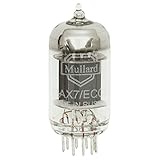
- Large sound stage with excellent detail
- Factory selected for low noise and lowest microphonic.
- Single tube
- ECC83/7025 equivalent
There is a loud whine or buzz
Look for switching harmonics coupling into the input, magnetic pickup from the transformer, inadequate B+ filtering, heater hum, shared battery-return impedance, poor grounding, or input wiring close to the converter. Change layout and return paths as well as filtering; adding capacitance alone may not address magnetic or ground-coupled noise.
The heater glows but there is no audio
A glowing heater does not prove that B+ is present, the tube is functional or biased correctly, the grid is at the intended DC potential, or the output is correctly coupled and loaded. Trace the signal stage by stage and verify DC operating conditions before replacing parts.
When to choose another approach
| Approach | Best fit | Trade-off |
|---|---|---|
| NE555-based converter | Educational or experimental builds where a discrete switching design is part of the goal | Requires transformer and driver design, noise control, measurement, and troubleshooting. |
| Modern DC–DC converter | Compact builds prioritizing repeatability, regulation, or efficiency | Verify isolation, output power, ripple, and switching-noise behavior; an advertised output voltage alone is not enough. |
| Conventional mains-powered tube supply | Builds where portability is unimportant and a traditional higher-voltage operating point is desired | Requires appropriate mains isolation, high-voltage design, enclosure, and safety practices. |
| Solid-state preamp | Clean, low-voltage gain where low noise, reliability, or battery operation matters more than a tube stage | Does not provide a real tube audio stage. |
| Low-voltage “starved-plate” tube circuit | Projects explicitly designed around low plate voltage | Not equivalent to a conventional high-voltage tube operating point. |
A TLC555 is another timer option. TI notes its CMOS construction and higher input impedance, which can allow smaller timing capacitors than bipolar NE555/LM555 devices; check the chosen part’s output behavior against the driver rather than assuming it is a drop-in transformer driver. TI TLC555 product information
Tube choice also changes the design. A 12AU7 generally favors lower gain and greater current drive than a 12AX7, but shared nine-pin bases do not make them interchangeable: recalculate bias, plate load, heater arrangement, and intended function. A separate 12AU7 cathode-follower design reports overall gain of approximately eight, but that is a result for that circuit, not a general tube specification. 12AU7 cathode-follower reference
Quick Recap
Product prices and availability are accurate as of the date/time indicated and are subject to change. Any price and availability information displayed on Amazon at the time of purchase will apply.

