
iTechGuides is reader-supported. When you buy through links on our site, we may earn an affiliate commission. As an Amazon Associate I earn from qualifying purchases. Learn more
A 2017 microfluidic method took lipid-stabilized bubbles that started larger than 100 µm and shrank them to a reported 1–7 µm range by applying vacuum through neighboring microchannels, with no further filtration needed for the result. The work was a laboratory device described in a 2017 Chemistry World news report and a 2017 paper in Soft Matter. Its main stated obstacle was production speed, and nothing in the reporting shows the system being used in a clinical setting.
What the 2017 method did
The subject is a set of microbubbles, not ordinary soap bubbles. Microbubbles are tiny gas bubbles with a shell, and they can act as contrast agents in ultrasound imaging. The problem the study addressed is size: the bubbles that a microfluidic device first produces are too large for the job, and the process needed to make them smaller and more uniform in one continuous step.


How the shrinking works
The Chemistry World report describes the process as a sequence of four stages inside one device:
- Generate larger bubbles. The system first produces lipid-stabilized bubbles larger than 100 µm in diameter.
- Route them through a serpentine channel. The bubbles flow through a winding microchannel.
- Apply vacuum beside the flow. Vacuum applied through adjacent microchannels shrinks the bubbles as they pass.
- Collect the output. The reported end product measures 1–7 µm, is described as stable and uniform in size, and, according to the report, did not need further filtration.
The vacuum approach is what distinguishes the method from generating small bubbles directly. The report contrasts it with conventional techniques, which it says can produce broad size distributions.
#1 Best Overall
Why bubble size matters for ultrasound
In ultrasound contrast imaging, injected bubbles vibrate at their resonant frequency when hit by ultrasound waves. A bubble of the right size scatters the sound much more strongly than the surrounding tissue, which makes blood vessels easier to see on the image. The Chemistry World report gives around 2 µm as the target size for this application. The 1–7 µm output range therefore covers the target, but the reporting does not establish how many bubbles fell within a narrow band around 2 µm.
The production bottleneck
The main limitation was throughput. In the 2017 report, Scott Tsai said that the device could take up to three years to make enough bubbles for one clinical procedure. He described an engineering goal of producing a procedure’s supply in about an hour. Both figures are statements about the 2017 device and a stated target. They are not measurements of current performance, and the reporting does not describe a later achievement of the goal.
Rank #2

- Neubaur-Improved (NI) Grid Pattern Version
- Microfluidic Chambers: Two chambers per slide with depths and volumes of 0.10 mm & 10 µL. Eliminates the need for coverslips and prevents sample carry over. Designed for convenience and cleanliness.
- High-Light Transmittance: For improved sample visibility and clarity.
- Uniform Sample Distribution: Microfluidic Air-walls and hydrophillic treatments of the chambers allow for the even distribution of sample cells and the prevention of air bubbles.
- Compatibility: Compatible with phase contrast microscopes and most available Automated Cell Counters.
Other uses the team discussed
The report also covers applications beyond medicine. Raffi Karshafian, who worked on the project, said: “‘[They] are being investigated in applications such as wastewater treatment, cleaning and disinfection of surfaces, and eradication of biofilms,’ explains Raffi Karshafian, who also worked on the project. ‘The effectiveness of these applications may potentially be improved through the utilization of monodisperse small bubbles’.” These are presented as potential areas of investigation. The article does not show that this device achieved any of those outcomes.
Do these 3 things before closing this tab:
1Scan for outdated or missing drivers - takes under a minute2Clear out junk files and repair common Windows errors3Fix the driver behind crashes, sound loss and screen glitchesWhat outside experts said
Eleanor Stride, an expert in biomedical ultrasonics at the University of Oxford, said: “It’s a very elegant idea to solve one of the challenges associated with using microfluidics for bubble fabrication.”
Rank #3
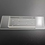
- VERSATILE STANDARD CHIP: Dual-width channels (50µm & 100µm) in a simple layout — perfect for proof-of-concept experiments and protocol development.
- ENTRY-LEVEL & AFFORDABLE: The most cost-effective way to start microfluidics — ideal for students, teaching labs and teams testing new protocols.
- STARTER KIT INCLUDED: Comes complete with PTFE tubing and a syringe, giving students and researchers everything needed to begin microfluidics experiments right out of the box.
- QUALITY PDMS/GLASS BUILD: RTV615 PDMS plasma-bonded to borosilicate glass; optical clarity for fluorescence and brightfield imaging.
- PRACTICAL FORM FACTOR: Compact 45x20mm size with multiple inlet/outlet ports for flexible fluid routing.
Steve Shih, a microfluidics expert at Concordia University, said: “What I love about it is that anyone can make these devices without any sort of specialized knowledge or background.”
How the approach compares with conventional generation
The report does not compare two commercial products. The only comparison it supports is on the axes it names, so the table below uses only those axes.
Rank #4
| Axis | Vacuum-shrinking microfluidic device (2017 report) | Conventional techniques |
|---|---|---|
| Size distribution | 1–7 µm, described as stable and uniform | Can produce broad distributions (Chemistry World, 2017) |
| Filtration needed after production | Not needed for the reported result (Chemistry World, 2017) | Not stated |
| Production rate | Up to three years for one procedure’s supply, per Scott Tsai in 2017; goal of about an hour | Not stated |
The underlying paper
The study is V. Gnyawali, B.-U. Moon, J. Kieda, R. Karshafian, M. C. Kolios, and S. S. H. Tsai, “Honey, I shrunk the bubbles: microfluidic vacuum shrinkage of lipid-stabilized microbubbles,” Soft Matter (2017), DOI: 10.1039/C7SM00128B. Toronto Metropolitan University’s Laboratory of Fields, Flows, and Interfaces lists the paper and the author group. Readers who want the device details, such as channel geometry and vacuum settings, should consult the paper itself; this article does not reproduce those parameters.
What is and is not established today
- Established in 2017: the shrinking method, the 1–7 µm output range, the around 2 µm target for ultrasound, and the production-rate limitation.
- Not established by the reporting: current commercial availability, regulatory status, clinical use, or whether the production rate has since reached the one-hour goal.
- Presented as potential: wastewater treatment, surface disinfection, and biofilm eradication.
Because the reporting is from 2017, anyone looking for the current state of this technology should check newer publications from the same groups rather than relying on the original news story.
Quick Recap
Best Value
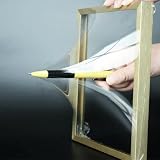
- 【Microfluidic Chip Packaging Film】 Full transparency, low temperature flexibility, good air permeability, thermal and chemical stability
- 【Microfluidic Chip Packaging Film】 Shore Hardness (A): 50, tensile strength (MPa): 4, tear strength (KN/m): 7
- 【Microfluidic Chip Packaging Film】 Elongation at break (%): 100, Elastic modulus: 1.7, Refractive index: 1.41, Transmittance (%): >95(2mm)
- 【Microfluidic Chip Packaging Film】 Using temperature range (C): -40 to 200, Dielectric strength (kV/mm): 12, Dielectric constant (1MHz): 2.7
- 【Microfluidic Chip Packaging Film】 1 Pcs/package
“
Product prices and availability are accurate as of the date/time indicated and are subject to change. Any price and availability information displayed on Amazon at the time of purchase will apply.

