
iTechGuides is reader-supported. When you buy through links on our site, we may earn an affiliate commission. As an Amazon Associate I earn from qualifying purchases. Learn more
Choose an automotive MCU against the ECU’s safety, thermal, timing, memory, network, security and lifecycle requirements—not by clock speed or a feature list alone. Start with the ECU’s hazards and operating conditions, then verify that the exact part number and package have the documentation, peripherals, software support and supply commitments your program needs.
1. Define the safety target and required evidence
Begin with the ECU hazard analysis and the safety requirements assigned to its functions. The required Automotive Safety Integrity Level (ASIL) depends on the hazards and risk analysis; it is not a rating to choose by preference or infer from the MCU’s marketing description.
Ask the supplier for the safety manual, failure modes, effects and diagnostic analysis (FMEDA), diagnostic-coverage data, assumptions of use and information about its safety processes. Check that the documentation applies to the exact device and intended use, and that the proposed architecture can meet the ECU’s safety requirements.
Recommended Free Tools
An MCU described as “safety-ready” or suitable for an ASIL does not certify the complete ECU, vehicle function or system. The integrator must still develop and validate the full safety case in context.
#1 Best Overall

- 2.4GHz Dual Mode WiFi + Bluetooth Development Board
- Support LWIP protocol, Freertos;ESP32 is a safe, reliable, and scalable to a variety of applications
- SupportThree Modes: AP, STA, and AP+STA
- Ultra-Low power consumption, Compatible with Arduino IDE
- 1PCS 30Pin ESP32 Development Board 2.4GHz WiFi Dual Cores Microcontroller Integrated with Antenna RF Low Noise Amplifiers Filters
2. Match AEC-Q100 qualification and temperature grade to the real thermal profile
AEC-Q100 is a component qualification standard; ISO 26262 addresses functional safety across the automotive development lifecycle. They answer different questions. AEC-Q100 qualification does not establish an ASIL, while safety collateral does not replace confirmation of the component’s qualification and operating limits.
Verify the qualification for the exact device and package, then compare its specified temperature grade with the expected junction-temperature profile. Ambient temperature is not junction temperature: the die can run hotter because of power dissipation, board design, enclosure and cooling. Use a thermal calculation or measurement for the intended installation rather than treating an under-hood ambient estimate as the MCU’s junction temperature.
Published manufacturer examples illustrate why the precise limit matters: Microchip documents Grade 0 automotive devices for operation from −40 °C to 150 °C, while STMicroelectronics lists SPC5 operation up to 165 °C junction temperature. These are portfolio or family claims, not a substitute for checking the data sheet and ordering code of the part under consideration.
3. Size compute resources for worst-case workload, not headline frequency
Build a workload budget for the most demanding operating state. Include control-loop execution, diagnostics, network handling, interrupt load, startup and fault reactions. Compare core count and architecture, clock range, DSP or floating-point support, accelerators, interrupt latency and memory bandwidth against the deadlines those workloads must meet.
Use measured or carefully estimated utilization and retain timing margin for peak load, diagnostic activity and future software changes. A higher clock frequency alone does not prove that a device will meet a deadline: memory contention, peripheral servicing, interrupt behavior and software efficiency also matter.
Rank #2

- 【ACEBOTT ESP32 Development Board】 - Powerful WiFi and wireless development board, driven by the rugged ESP 32 module, seamlessly integrated with Arduino IDE. With Hall sensors, high-speed SDIO/SPI, UART, I2S and I2C, it is the cornerstone of IoT and smart home innovation.
- 【Wi-Fi/Bluetooth and Arduino Cloud Compatibility】 - This board uses 2.4GHz dual-mode WiFi and wireless chips with low-power technology, which are RoHS-compliant, simplifying wireless communication and allowing you to easily connect devices and platforms. Whether you are using a compatible Arduino IDE or exploring other development environments, our board can easily adapt to your needs.
- 【Improved and Professional Edition】 - All IO pins are brought out for easy development; no additional breadboard is required; the Type-C interface is equipped with electrostatic discharge protection diodes and transient voltage suppression diodes to protect the chip from damage by electrostatic breakdown and various surge pulses. In addition, it is equipped with a freeRTOS operating system, which is very suitable for the Internet of Things, smart homes, and building smart robots/game consoles.
- 【Easy to Use】- The ACEBOTT ESP-32 Development Board includes everything you need to support the microcontroller. Just connect it to a computer via a USB cable or use an AC-DC adapter or battery to power it to start using it. Whether you are an experienced developer or a hobbyist, this development board can provide you with the tools you need for unlimited innovation.
- 【 Install Plugins And Download Drivers】: This ESP32 development board includes detailed instructions on how to download plugins and all necessary programs and codes from the network environment. The path is: ACEBOTT official website - Resources - WIKI.
For scale, ST describes SPC5 devices with up to three cores at 200 MHz, and Infineon describes TRAVEO T2G configurations up to 320 MHz. Those are maximum family-level figures in the cited product descriptions; they do not establish the performance of every device in either family or of a particular ECU workload.
4. Check memory integrity, endurance and retention
Compare flash and RAM capacity against the application, bootloader, diagnostic data and planned update strategy. Then inspect what protection applies to each memory region: ECC coverage, error reporting, boot-memory protection, retention conditions and flash write endurance. Confirm whether detected errors can be reported and handled in the way the ECU safety concept requires.
Outdated Drivers Are Slowing You Down
One free scan finds every outdated or missing driver and matches the right update for your exact hardware.Free scan · exact hardware matchPC Slower Than It Used to Be?
A free scan shows the junk files, broken settings and background clutter dragging Windows down - then fixes them in one click.Free scan · Windows 10 & 11ST lists ECC flash, 250 kcycles of endurance and high-temperature data retention for SPC5. Treat these as family-level published specifications until the exact ordering code, temperature grade and relevant data-sheet conditions confirm that they apply. Check the endurance definition and test conditions against the expected write pattern; frequent logging or repeated updates can make endurance more consequential than total capacity.
5. Map real-time peripherals to every sensor and actuator
Make a signal-and-timing inventory before selecting a part. Count analog inputs and required ADC resolution, PWM outputs, timer and capture/compare channels, DMA transfers, watchdogs and reset-supervision functions. Include synchronization, sampling windows and response deadlines, not just pin totals.
Also determine whether the MCU’s analog front end is adequate or whether the design needs external signal conditioning or conversion. A family feature list cannot establish that the precise variant has enough channels, the required routing or the right timing behavior.
Rank #3

- Maximum performance: the Pro micro microcontroller development board runs at 5 V/16 MHz and supported by IDE V1.0.1 for smooth programming. Suitable for Arduino.
- Versatile connections: Pro micro with 4 x 10-bit ADC pins, 12 x digital I/Os and serial Rx and Tx hardware connections, you have all the ports you need.
- Easy programming: Pro micro simply connect the motherboard to the on-board micro USB port and program it. If it is not detected, just install the driver.
- Multifunctional I/O: Pro micro there are 54 digital input/output pins available, including analogue inputs/outputs, as well as interfaces such as PWM, SPI, I2C etc., which offer a wealth of hardware connection options.
- Good compatibility: the seamless integration with the Arduino IDE and the extensive development tools and libraries ensure a smooth learning curve and make it a good choice for beginners.
Microchip lists power-on reset, brown-out reset, a windowed watchdog and CRC among its safety features. Verify the implementation details and configuration options in the selected device’s documentation, then map each required sensor and actuator path to an available peripheral and pin.
The Tool Desk
Outbyte Driver Updater FREEFix the driver behind crashes, sound loss and screen glitchesFind Drivers →Outbyte PC Repair FREERepair Windows errors before they cause bigger problemsFix Now →6. Verify vehicle-network interfaces and external components
List the vehicle buses the ECU must support and check the exact MCU variant for native channels, protocol capability and simultaneous-use limits. Consider message filtering, timestamping, wake-up behavior and how each interface connects to the rest of the system. A controller interface may still require an external transceiver and associated protection circuitry.
Published portfolio examples include CAN, CAN FD, LIN, SENT and 10BASE-T1S for Microchip; CAN FD, LIN and Ethernet AVB for Infineon TRAVEO T2G; and CAN FD, Ethernet, LIN and FlexRay for ST SPC5. These are manufacturer-stated family or portfolio capabilities. Confirm channel count, supported modes, pin availability and external hardware requirements for the exact part and design.
7. Evaluate cybersecurity hardware and the update path
For connected or serviceable ECUs, assess the complete chain from startup to field maintenance. Check for secure boot, protected key storage, cryptographic acceleration, a true random-number generator, authenticated diagnostics, secure firmware updates and controls that restrict debug access. Determine where keys are provisioned and how credentials, failed updates and recovery are handled.
Infineon states that TRAVEO T2G supports ISO 21434 and OTA updates. ST lists HSM, EVITA and SHE-compliant security features, and Microchip documents secure boot, secure upgrades and secure communication in its automotive portfolio. These statements identify manufacturer-described capabilities; they do not by themselves show that a particular ECU meets its cybersecurity requirements. Confirm the exact device features, software support and integration responsibilities.
Free tools Windows power users keep installed
One-click scans. No signup required.
Rank #4
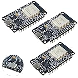
- High-performance dual-core processor – ESP32S is equipped with a powerful dual-core 32-bit CPU with a main frequency of up to 240MHz, providing smooth and efficient computing power for IoT and embedded applications.
- Wi-Fi & Bluetooth dual-mode support – Integrated 2.4GHz Wi-Fi and low-power Bluetooth, supporting wireless data transmission, remote control and smart device connection.
- Rich interfaces and functions – Provides GPIO, UART, SPI, I2C and other interfaces, supports touch sensing, infrared remote control, DAC and other functions, suitable for a variety of electronic projects.
- Low-power design – With multiple power saving modes, supports deep sleep and ultra-low power operation, suitable for battery-powered Internet of Things (IoT) devices and remote monitoring systems.
- Compatible with multiple development environments – Supports for Arduino IDE, for ESP-IDF, for MicroPython and for PlatformIO, easy to develop, suitable for beginners and advanced developers to quickly build smart applications.
8. Understand power, clock and fault behavior
Review the operating-voltage range, low-power modes, brown-out thresholds, clock monitoring, watchdog independence, reset causes and recovery paths. Consider how the ECU should behave during battery transients, startup and sleep, and after a single fault. The MCU must recover—or enter a defined safe state—in a way that fits the system design.
Read the reset and clock-monitor documentation alongside the software architecture. A listed monitor or watchdog is useful only if its coverage, independence, configuration and response are appropriate for the failure modes the ECU must address.
9. Compare software support and safety collateral
Check toolchain, compiler and debugger support, RTOS integrations, configuration tools, reference designs, errata and access to safety documentation such as manuals and FMEDAs. For an AUTOSAR design, confirm the required MCAL support, compatible versions and licensing before committing to a family.
Microchip describes MCAL software developed in accordance with Automotive SPICE to enable AUTOSAR compliance. This is a supplier statement about its software development approach; confirm which MCAL release supports the target device and AUTOSAR version, what configuration and integration work remains, and what support terms apply.
10. Confirm lifecycle and supply continuity
Review published longevity statements, product-change-notification (PCN) and end-of-life policies, manufacturing and quality information, package options and supply capacity. Ask how the supplier will communicate changes and whether your program can manage a package or silicon revision change. If continuity is critical, assess whether a genuine second-source strategy is possible; a pin-compatible alternative is not automatically software-, safety- or qualification-compatible.
Best Value

- Dual core ESP-32 development board, 2.4GHz dual mode development board.There are two touch buttons, one is reset, the other is enable module to enter the halberd program mode.
- The module is ESP--32 module, the peripheral uses the USB serial port chip CP2102 to expand the micro USB interface, which can be directly debugged by a USB connected computer, and the data transmission is fast and stable.
- ESP32 shield 30P expansion board, supports two power supply : DC 6.5-16v and USB 5V
- ESP32 development board GPIO breakout board GVS output power supply can be 5V or 3.3V, which is more convenient to match the external 5V electronic module sensor.
- This esp32 kit is safe, reliable, and scalable to a variety of applications. Stable and highly reliable. Great contact and stable signal transmission for your program
ST states, “Longevity: 15 years guaranteed, extended to 20 years for SPC56 and SPC58 families.” This is a supplier claim for the named families, not a blanket guarantee for every ST MCU or an automatic program-level commitment. Verify the exact part, applicable terms and supply arrangements with the supplier for your project.
Compare candidates against the same requirements
Once multiple families pass the ECU’s mandatory requirements, compare them on the same evidence rather than treating a single headline specification as decisive. The examples below capture only published claims identified for these families; they are not a complete specification comparison.
| Family or portfolio | Published example | What to verify for the selected part |
|---|---|---|
| Microchip automotive MCU portfolio | Grade 0 devices documented for −40 °C to 150 °C operation; listed interfaces include CAN, CAN FD, LIN, SENT and 10BASE-T1S. | Exact grade, package, interface mix, safety evidence, software support and specifications for the ordering code. |
| Infineon TRAVEO T2G | Configurations described up to 320 MHz; listed interfaces include CAN FD, LIN and Ethernet AVB. | Exact core configuration, supported interfaces, safety and security documentation, package and temperature limits. |
| ST SPC5 | Up to three cores at 200 MHz; operation up to 165 °C junction temperature; ECC flash, 250 kcycles endurance and high-temperature data retention are listed. | Whether each figure applies to the exact device, ordering code, grade and documented operating conditions. |
Before choosing between qualifying candidates, compare required ASIL evidence and diagnostic coverage, thermal margin, worst-case compute performance, memory protections and endurance, network support, security and update mechanisms, software collateral, package compatibility, cost and documented supply terms. Keep mandatory requirements separate from preferences so a strong score in one area cannot hide a failure in a safety or timing requirement.
A practical selection sequence
- Document ECU hazards, required ASIL evidence, operating conditions, workload deadlines, signals, buses, security needs and program lifetime.
- Eliminate parts that fail mandatory qualification, thermal, safety, timing, memory or interface requirements.
- For each remaining ordering code, check its data sheet, errata, package pinout and supplier safety, security and software collateral.
- Validate timing, thermal behavior, peripheral allocation and fault responses in the intended ECU design; do not rely on family maxima alone.
- Compare lifecycle terms, PCN/EOL policy, supply arrangements, development effort and total program fit before freezing the design.
The best automotive MCU is the one whose exact configuration can satisfy the ECU’s requirements with documented evidence and enough design margin—and whose software and supply support fit the program’s life.
Quick Recap
Product prices and availability are accurate as of the date/time indicated and are subject to change. Any price and availability information displayed on Amazon at the time of purchase will apply.

