
PC Slower Than It Used to Be?
A free scan shows the junk files, broken settings and background clutter dragging Windows down - then fixes them in one click.Free scan · Windows 10 & 11Outdated Drivers Are Slowing You Down
One free scan finds every outdated or missing driver and matches the right update for your exact hardware.Free scan · exact hardware matchiTechGuides is reader-supported. When you buy through links on our site, we may earn an affiliate commission. As an Amazon Associate I earn from qualifying purchases. Learn more
A 3D-printed gear train works only when its teeth, clearance, axis spacing, support structure, material and manufacturing accuracy work together. There is no single clearance or safe torque figure that applies to every printer and design. Treat a first print as a fit test, then refine the mesh for the actual material, process and operating load.
How much clearance or tolerance should be added to a 3D-printed gear mesh?
Backlash is the tangential clearance between the teeth of two meshing gears. It lets the teeth move without being squeezed together, but its actual value depends on tooth thickness, center distance, manufacturing deviations and operating conditions. ISO 21771-2:2025 formalizes calculation relationships for gear geometry; it does not prescribe the tooth thickness or tolerance a designer should choose. See the ISO 21771-2:2025 scope and standard page.
As a starting point for general printed-part fits—not a gear-flank backlash specification—FRCDesign gives a range of 0.1–0.5 mm (0.004–0.020 inches), depending on fit type, and advises finding the tolerance that works on the specific printer. The page does not state a publication date. Use the range to plan a small calibration print rather than applying one value to every gear mesh. FRCDesign’s 3D-printing design guidance
Quick wins for a faster PC:
Scan for outdated or missing drivers - takes under a minuteDriver Scan →Repair Windows errors before they cause bigger problemsFix Now →Fix the driver behind crashes, sound loss and screen glitchesFind Drivers →- Print a small test using the intended printer, material and process, with representative gear geometry and several clearance choices.
- Check whether the parts assemble and rotate freely, and note excessive looseness, binding or inconsistent contact.
- Adjust the design based on the test before printing the full mechanism. A test made with different material or process may not predict the final fit.
Do not confuse assembly clearance with backlash at the teeth. Gear tooth thickness and center distance determine the working mesh, while printer-specific dimensional variation can shift the result. For operating principles, a Delrin molded-gear reference notes that thermal variation, shrinkage and changes in the housing can alter backlash: too little can cause seizing or rapid failure, while excess can increase wear. Those observations concern molded gears, so they are guidance about factors to consider—not printed-gear clearance values. Delrin’s general gear design principles
#1 Best Overall

- Extruder Gear Kit for Elegoo Centauri Carbon
- Carbon fibre version - SKD11 metal drive gear and POM handle, equipped with GFM wear-resistant bearings, high hardness and durable 3D printer extruder hot end replacement parts
- The black large gear and handle are made of POM material, ensuring low friction, excellent wear resistance and high transmission accuracy, effectively reducing consumable feeding errors
- GFM wear-resistant bearings for smooth, effortless operation: The handle is equipped with high-precision GFM bearings, reducing friction and offering excellent self-lubricating performance, providing a smooth, maintenance-free user experience
- Excellent hardness, outstanding load-bearing capacity and durable performance, suitable for continuous 3D printing use
Why do my 3D-printed gears bind?
Binding usually means the assembled system has less working clearance than the teeth need, or that the axes are not held in the intended relationship. A gear profile that looks correct on its own can still fail when the shafts, bearings or housing locate it incorrectly. AGMA 909-A06 emphasizes the relationship between gear geometry, layout, housings, shafts, bearings and materials in plastic gear transmission design. AGMA 909-A06
- Tooth fit: The printed teeth may be thicker or less accurate than intended, reducing clearance.
- Center distance: If the gear axes are closer together than the design requires, the teeth can be forced into each other.
- Support and alignment: Shaft, bearing or housing dimensions can shift the axes or allow them to move under load.
- Operating changes: Temperature and dimensional changes in surrounding parts can affect the mesh during use.
Inspect the gears in the assembled mechanism rather than judging tooth geometry in isolation. If binding is present, check axis spacing and support first, then test a revised fit on the actual printer and material. Increasing clearance indiscriminately can trade binding for excess backlash and wear.
Rank #2
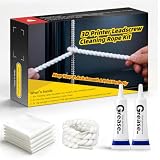
- QUICK-CLEAN IN MINUTES — NO TOOLS REQUIRED, Skip the hassle of taking your printer apart. Our leadscrew cleaning rope kit lets you maintain your Z-axis rod in under 5 minutes — just apply, scrub, wipe, and lubricate. No special tools needed, no re-alignment headaches, no risk of disturbing your carefully tuned machine. It’s the fastest way to keep your leadscrew in top condition without a single disassembly step.
- 40 REUSABLE CLEANING ROPES — SCRATCH-FREE & DURABLE, Each rope is crafted from high-strength polyester fiber that aggressively traps dust, filament debris, and old grease without scratching precision lead screw threads. Ropes are fully washable and reusable — one kit gives you 40+ cleaning cycles. That’s enough to maintain multiple printers for a full year.
- COMPLETE ALL-IN-ONE MAINTENANCE KIT, Everything you need is in the box: 40× premium cleaning ropes, 5× ultra-absorbent lint-free cloths (anti-static, streak-free), and 2× precision 10g PTFE grease syringes with temperature-resistant, low-odor formula. No extra trips to the hardware store — unbox and clean immediately.
- HELPS REDUCE Z-WOBBLE & SUPPORTS LEADSCREW LONGEVITY, A dirty or dry leadscrew is a common contributor to Z-axis inconsistencies, layer lines, and print artifacts. Regular cleaning and lubrication helps restore smooth Z-axis motion, supports consistent layer quality on tall prints, and promotes the long-term performance of your lead screw and nut assembly. Think of it as routine maintenance for your 3D printer.
- UNIVERSAL FIT FOR ALL MAJOR FDM PRINTERS, Engineered to fit T8, T10, T12, and T14 trapezoidal lead screws found on virtually every popular FDM 3D printer: Creality Ender 3 / V2 / Pro / S1 / Neo, CR-10 series, Prusa i3 MK3S / MK4 / Mini+, Artillery Sidewinder X1 / Genius, Sovol SV01-04, Elegoo Neptune, Tronxy, and most CNC machines with standard threaded rods.
How do FDM and SLS compare for printed polymer spur gears?
A 2025 study by Levente Czégé and Gábor Ruzicska compared FDM- and SLS-printed polymer spur gears with an injection-molded reference. In the samples studied, FDM had lower reported deviations in the measured gear dimensions, while SLS produced lower average surface roughness. This is a result for the study’s samples and methods, not a universal ranking of the two processes. Czégé and Ruzicska, “Geometrical Analysis of 3D-Printed Polymer Spur Gears,” Machines 13 (2025)
| Measure reported in the 2025 study | FDM samples | SLS samples |
|---|---|---|
| Mean relative error for chordal thickness | 1.96 mm | 5.64 mm |
| Average relative error for pin measurement | 0.193 mm | 0.616 mm |
| Average deviation across a four-tooth span | 0.153 mm | 0.773 mm |
| Average surface roughness | Ra 9.28 µm | Ra 2.65 µm |
The study reports the figures above for its samples; they do not predict the accuracy or finish of a different printer, material or gear design. The authors found SLS samples smoother than the FDM samples, but still rougher than the injection-molded reference. Process choice should therefore be based on the specific design and desired outcome, then validated with parts made under the intended conditions.
Rank #3

- This is an all-steel one-piece machined integrated filament driving gears, More sturdy , longer lifetime
- Compatible with Prusa i3 MK3 MK2/MK2S/MK2.5 MK3S MK3.5S 3D Printer
- The Drive gears are made from Hardened steel material. After heat treatment,,hardeness reach 55HRC, with high precision.
- Material : hardened steel, black treatment to advoid rusting
What loads are appropriate for a 3D-printed gear?
The available guidance supports printed gears for low-load or secondary mechanisms, but cautions against using them for high-torque service. FRCDesign warns that motor pinions and drive gears can wear quickly and says high-torque applications are generally not well suited to 3D-printed gears. It does not establish a universal torque rating or lifetime. FRCDesign’s 3D-printing design guidance
To improve tooth strength, the FRCDesign handbook identifies increasing face width and choosing a lower diametral pitch—fewer teeth per pitch-circle length, which means thicker teeth—as design options. These changes do not create a guaranteed load capacity: the complete design still depends on gear geometry, material behavior, shafts, bearings, housing and operating conditions. Stratasys’s gear-systems lesson guide also calls attention to material thickness, layer thickness and printer tolerances. Stratasys Lesson Guide: Gear Systems
Rank #4

- 【Upgraded 68-in-1 3D Printer Tools Kit, 1-Year Warranty】Designed by a Team of 15-Year 3D Printing Enthusiasts, the kit includes all essential tools. From wire cutters to needle-nose pliers, it cuts and trims PLA and other filaments precisely and fast. From high-quality hand drill with 10 drill bits to 5 types of metal files, your 3D printing range expands to a wide variety of materials. Upgraded durable 900D Oxford fabric with orange tags for quick and easy organization.
- 【Scrapers for Flawless Removal 3D Printed Models】One Stainless Steel removal scraper features a 15-degree angled (0.5mm thickness, 1.57-inch length), providing optimal leverage and precision, perfect for models like 3D printed dragon eggs and ideal for PETG, ABS, PLA+. The smaller orange scraper, with 10 extra-thin flat blades, offers pinpoint accuracy, making it ideal for removing small models with precision, such as 3D printed toys.
- 【1 Deburring Tool & 10 HSS BS1010 Swivel Blades】Our model polishing tools include 3 engraving knives with 9 types of blades, 5 different metal files and a 360° swivel-head deburring tool. This deburring tool conforms to uneven shapes, surfaces, edges, and ideal for PETG, ABS, PLA+ 3D printed models. Additionally, we add 10 EXTRA razor-sharp BS1010 blades made of tempered high-speed steel. HSS is known for being stronger and lasting 80% longer than regular steel.
- 【Nozzle Cleaning Needles, Brushes & Tweezers】To avoid inconsistent filament extrusion caused by a clogged nozzle, we provide 5 types of cleaning needles, (0.2mm, 0.25mm, 0.3mm, 0.35mm, 0.4mm), suitable for most 1.75mm PLA/ABS filament 3D printers. 3 Different cleaning brushes — made of Brass, Stainless Steel and Nylon for different cleaning conditions. Bent, Straight, Flat-Tip tweezers are added for precision cleaning.
- 【3D Printer Accessories Gifts Must-Have】4 cut-resistant finger cots to protect your fingers while working. A black sleeve case makes it easy to find, organize, store, and transport your tools. It keeps all 3D printer tools in excellent condition by protecting them from dust, debris, and moisture —ensuring all tools stay sharp and ready for your next 3D printed task. Your Satisfaction, Our Promise: All products come with 1-YEAR warranty and all questions will be answered within 12 hours.
What tool can I use to measure gear teeth?
A gear-tooth vernier caliper, also called a gear tool caliper, can measure chordal tooth thickness. Czégé and Ruzicska used a gear tool caliper for chordal thickness in their 2025 study. That is an example of a suitable measurement method, not an endorsement of a particular commercial tool or model.
Recommended Free Tools
Measurement is only useful when you know what dimension you are checking and how it relates to the intended gear geometry. The study also examined pin measurements, span over four teeth, 3D scans and surface roughness; these measure different aspects of the gear and should not be treated as interchangeable checks. For practical iteration, compare the printed part with the intended dimension and assess its assembled mesh in the actual shaft-and-housing layout.
Best Value

- ENHANCE PRINT PRECISION: Use this 10g (0.3oz/0.02lb) oilstick 3d printer lube to improve sliding consistency on lead screws and shafts. The odorless, non-toxic formula reduces friction deviations, helping you achieve higher printing accuracy and detail
- REDUCE NOISE AND WEAR: Apply this non-flowing 3d printer lubricant to linear rails to minimize grinding sounds. Its non-drying formula creates a protective layer that lowers component wear, helping you extend the lifespan of your moving equipment parts
- WIDE TEMPERATURE STABILITY: Rated for -20°C to 120°C (-68℉ to 248℉), this 3d printer grease maintains consistency without thinning. It supports your reliable movement during long prints, preventing lubrication failure in varying thermal environments
- RUST PROTECTION FOR METAL: This 3d printer oil and grease acts as a moisture barrier for gears and bearings. It prevents corrosion on 3d printer parts & accessories and engraving machines, keeping your systems running smoothly for years
- EASY MAINTENANCE OIL PEN: The 4-pack 3d printer oil pen allows for precise application without drips. This 3d printer lube and grease kit and 3d printer lube pen simplify maintenance, making it easy for you to apply gear grease without any tools
Why the complete gear train matters
Gear geometry is only one part of a functioning transmission. Center distance, shaft alignment, bearing support, housing stiffness, tooth thickness, material behavior and print capability all affect whether a mesh turns freely and lasts. ISO 21771-2:2025 covers calculation relationships for external and internal cylindrical involute spur and helical gears, involute worms and crossed-axis gears, racks, and sector gears; its formulas apply across sizes, materials and manufacturing methods, but it does not select a designer’s desired tooth thickness or tolerance. For a working printed train, pair the geometry with a printer-specific fit test and a layout that locates the axes reliably.
Quick Recap
Product prices and availability are accurate as of the date/time indicated and are subject to change. Any price and availability information displayed on Amazon at the time of purchase will apply.

