
Recommended Free Tools
iTechGuides is reader-supported. When you buy through links on our site, we may earn an affiliate commission. As an Amazon Associate I earn from qualifying purchases. Learn more
Yes—often, if it is a bare brushed 12V DC motor and the design is engineered for it. A 24V PWM driver applies approximately 24V during each on-time and 0V during off-time; at 50% duty cycle, the first-order average is about 12V. That does not make the motor electrically identical to one powered from a regulated 12V rail. The motor still experiences 24V pulses, high startup and stall current, current ripple, switching transients and possible overspeed.
Use a 24V-rated H-bridge, enforce a duty limit based on the highest actual supply voltage, provide inductive-load and transient protection, and validate current, temperature and speed. If the motor must receive a true 12V rail or a software fault must not expose it to 24V pulses, install a correctly sized 24-to-12V buck converter before the motor driver.
What PWM from 24V actually does
For an ideal switch, the approximate average applied voltage is:
What’s actually slowing this PC down?
Pick the symptom - the matching free tool is one click away.
Vavg ≈ Vsupply × D
where D is duty cycle from 0 to 1. With a 24.0V supply, 25% duty is approximately 6V average, 50% is 12V, 75% is 18V and 100% is 24V. PWM motor stages behave broadly like switching step-down converters, although the motor’s inductance, speed, load and freewheel path determine the actual current and torque waveform. See maxon’s PWM power-stage explanation.
#1 Best Overall

- 6-12V Mini DC Motor -- This compact brushed DC motor is designed for 6V to 12V applications, making it suitable for RC cars, DIY electronics, small electric drills, toy cars, model projects, and hobby repair work.
- 2.3mm Shaft for DIY Compatibility -- The motor features a 2.3mm / 0.09 inch output shaft with approximately 12mm / 0.47 inch shaft length, suitable for compatible gears, pulleys, couplers, and DIY mechanical assemblies.
- Great for RC and Power Wheels Projects -- A practical replacement motor for compatible Traxxas RC vehicles, Power Wheels, toy cars, model cars, and other small motorized equipment. Please check the original motor size, voltage, shaft diameter, and wiring before ordering.
- High Speed, High Torque Performance -- Built for strong output in a small size,low noise, Max 12000RPM DC motor provides reliable speed and torque for replacement, upgrade, and DIY power applications.
- Wide Range of Uses -- Ideal for PCB projects, science experiments, robotics, hobby models, small electric tools, repair parts, DIY hand electric drills, and custom motorized builds.
This is an average-voltage approximation, not a safety certification. During every on interval the winding is exposed to roughly 24V minus driver losses. A mechanical load and winding inductance smooth some effects, but they do not turn the waveform into a continuous 12V supply.
How to calculate the duty-cycle ceiling
For a nominal 12V target:
Dlimit ≈ Vmotor,target ÷ Vsupply,max
| Highest real supply voltage | 12V target duty (first-order) |
|---|---|
| 24.0V | 12 ÷ 24 = 50.0% |
| 25.2V | 12 ÷ 25.2 ≈ 47.6% |
Use the highest measured or specified voltage, including a battery’s charging voltage, supply tolerance, wiring overshoot and regeneration. Start below the calculated ceiling and increase only after checking current, speed and temperature. A commonly cited 50% approximation for a 24V PWM supply driving a 12V motor is discussed in the Pololu forum; it is not a guarantee for every motor.
For an 8-bit controller with a 25.2V maximum source:
The Tool Desk
Outbyte PC Repair FREERepair Windows errors before they cause bigger problemsFix Now →Outbyte Driver Updater FREEFix the driver behind crashes, sound loss and screen glitchesFind Drivers →Rank #2
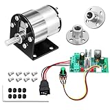
- Complete 5-in-1 power bundle: Each set includes 1 JGB37-520 geared motor with bracket, 1 CCM6N PWM speed controller, 2 pieces of 6mm flange couplings, and essential mounting screws. A ready-to-assemble solution for your miniature automation project
- 60RPM High torque for lifting: engineered for heavy-duty automation and powerful movement; With a superior 2.0kgf.cm load torque, it is perfect for mechanical arms, tank tracks, and heavy-load robotic platforms that demand maximum pushing power.
- Standard 6mm D-shaped shaft: Features a precision 6mm D-shaped output shaft for nice toughness and impact resistance. Ideally matched with the 0.24 inch (6mm) inner diameter flange couplings to ensure a secure, non-slip connection for robotics and DIY models
- CCM6N PWM controller: Take control with a professional 6A rated regulator (180W capacity). The oversized capacity provides extra safety headroom and prevents overheating, allowing smooth 0 percent to 100 percent speed range adjustment via the knob
- Versatile industrial DIY use: engineered for heavy-duty robotics and high-torque automation; featuring a zinc alloy casing, this 60RPM kit ensures stable, low-noise performance for mechanical arms, tank tracks, and smart locks; a robust power solution for engineers and makers.
const float supply_max = 25.2f;
const float motor_target = 12.0f;
float duty_limit = motor_target / supply_max;  // about 0.476
uint8_t pwm_limit = (uint8_t)(255.0f * duty_limit); // about 121
Do not copy an analogWrite() value between platforms: PWM resolution, polarity, timer frequency and driver interface differ.
Why 50% duty is not automatically safe
Instantaneous winding voltage
The 24V pulse can produce a substantially steeper current rise than a 12V pulse. Driver voltage drop and inductance modify the waveform, but the winding insulation, brushes and commutator still experience the higher pulse amplitude.
Startup and stall current
At zero speed, back electromotive force is absent. A useful upper-bound estimate is:
Rank #3
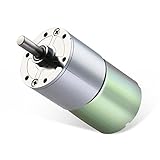
- 【ALL-METAL GEARS】: High-temperature resistance, high abrasion resistance, strong load capacity, sturdy and durable, effectively protect the gear box motor body.
- 【PURE COPPER WIRE CORE ROTOR】: With precision winding technology, the geared motor power instant increased by 30%.
- 【D SHAPED OUTPUT SHAFT】: Using high hardness steel, good toughness, impact resistance, the quality of the bearing and the service life of the gear motor are improved, extremely durable.
- 【POSITIVE-NEGATIVE ROTATION】: You also can adjust the speed, but the motor speed can only be reduced, can not be raised. Low noise and high torque, such as 10rpm can drive 15 kilograms.
- 【RELIABLE GURANTEE】: Any quality issues, we promise 100% unconditional return service. If you need other voltage and rpm, please feel free to contact us!
Istall ≈ V ÷ Rwinding
A 24V pulse can therefore drive roughly twice the initial resistive current of a 12V pulse, subject to inductance, PWM timing, wiring resistance and the driver’s current limit. Select the driver and protection for stall or peak current, not just normal running current. Switching designs also distinguish average from peak current; see Richtek’s current-sizing guidance.
Quick wins for a faster PC:
Scan for outdated or missing drivers - takes under a minuteDriver Scan →Clear out junk files and repair common Windows errorsFree Scan →RMS heating
Copper loss is approximately:
Pcopper = IRMS2R
A low average supply current reading can hide high pulsed or stall current. The real RMS value depends on inductance, PWM frequency, speed, load and whether the driver coasts, brakes or actively recirculates.
Speed, brushes and mechanics
Light load can let the motor overspeed if a duty limit is bypassed. Higher pulse current can increase brush and commutator stress, torque ripple and acoustic noise. Gearboxes, pumps and actuators may have separate speed, stall and reversing limits.
Rank #4
- 【ALL-METAL GEARS】: High-temperature resistance, high abrasion resistance, strong load capacity, sturdy and durable, effectively protect the gear box motor body.
- 【PURE COPPER WIRE CORE ROTOR】: With precision winding technology, the geared motor power instant increased by 30%.
- 【D SHAPED OUTPUT SHAFT】: Using high hardness steel, good toughness, impact resistance, the quality of the bearing and the service life of the gear motor are improved, extremely durable.
- 【POSITIVE-NEGATIVE ROTATION】: You also can adjust the speed, but the motor speed can only be reduced, can not be raised. Low noise and high torque, such as 10rpm can drive 15 kilograms.
- 【RELIABLE GURANTEE】: Any quality issues, we promise 100% unconditional return service. If you need other voltage and rpm, please feel free to contact us!
Confirm the motor type first
- Brushed DC motor: suitable for a correctly rated H-bridge or protected MOSFET stage.
- BLDC motor: requires a three-phase commutation controller; a brushed H-bridge is not sufficient. For example, TI’s DRV10987 is a dedicated sensorless BLDC driver.
- Fan or electronically commutated motor: may contain internal electronics and may require a designated PWM input rather than chopped power.
- Gearmotor, pump or actuator: check gearbox, hydraulic or load-transient limits in addition to motor ratings.
Recommended wiring for a brushed motor
24 V supply +  ───────── VM / driver supply+
24 V supply −  ───────── GND
MCU PWM       ───────── PWM input
MCU DIR       ───────── DIR input (if provided)
Driver OUTA   ───────── Motor terminal 1
Driver OUTB ───────── Motor terminal 2- Connect logic ground as required by the driver’s documentation.
- Never connect the motor to a microcontroller GPIO.
- Place the specified bulk capacitor close to the driver’s supply pins.
- Use a fuse or electronic protection suited to wiring and stall energy.
- Keep high-current paths short and appropriately sized; separate them from sensitive logic wiring.
- Use the driver’s integrated recirculation path or the externally specified flyback diode. PWM motor circuits commonly include a clamp path for inductive energy; examples are shown by Microchip and Analog Devices.
Choosing the motor driver
Check every item below in the exact datasheet, rather than relying on a board’s headline current number.
- Voltage: continuous operating range and absolute maximum, with margin for ripple, regeneration and spikes.
- Current: continuous thermal rating and peak/current-limit capability for startup and stall.
- Inductive-load topology: safe freewheel paths and documented diode requirements.
- Control interface: compatible logic levels, PWM polarity, enable behavior and fault outputs.
- Protection: overcurrent, overtemperature, undervoltage, reverse-polarity and short-circuit features.
- Thermal design: ratings at your ambient temperature, copper area, enclosure and heatsinking.
- Dynamic behavior: coast, brake and reversal modes, current sensing and fault-state behavior.
Examples illustrate why specifications are not interchangeable: NXP’s MC33926 is a 5–28V H-bridge with PWM specified up to 20kHz, while Pololu’s G2 24v13 is specified for 6.5–40V and PWM up to 100kHz under its stated conditions. A nominally “24V” driver with a 28V absolute maximum may have little transient margin on a 24V bus; Pololu discusses supply-ripple headroom at this motor-controller reference.
Selecting PWM frequency
| Lower frequency | Higher frequency |
|---|---|
| More audible whine and current ripple | Less audible noise and often smoother current |
| Lower switching losses | Higher switching losses, EMI and driver heating |
| Possible torque pulsation | May reduce ripple but can shrink usable duty range |
Several kilohertz to about 20kHz is a possible starting range, not a universal prescription. Respect the selected driver’s limits: MC33926 is specified to 20kHz, Pololu G2 24v13 to 100kHz, and the Pololu Simple High-Power Motor Controller 24v12 provides an adjustable 1–22kHz range. Very high frequencies can increase losses and dead-time effects; Pololu documents reduced available duty at high duty cycles in some 40kHz operation.
Best Value
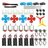
- Pay attention: Please read the instructions or pictures carefully, use the correct circuit diagram to avoid short circuit, short circuit will produce high temperature and Causing accessory damage
- Shaft Propeller Aperture:2mm/0.078"; Diameter:60mm/2.36"; Number of vane:4 vane and 3 vane;colour:Red & Blue & Yellow&Green&Clear(Random Color)
- DC Motors Color:Siler+Red;Voltage:DC 3V-12V;No-load speed: 9000RPM- 25000RPM ±10%; Motor Body Diameter:27mm/1.06";Shaft Size:10x2.0mm/0.39"x0.08"(L*D);Motor Body Length;38mm/1.46"
- High torque Strong magnetic Brushed Electric 130 MOTOR, can be used for Science Educational models, DIY STEM toys, etc.. It is recommended to use a 3V battery drive to avoid high-speed operation affecting the motor life.
- Package including:6pcs DC motor,6pcs 9V Battery Clip Connector,6pcs 2 x AA Battery Holder,6pcs motor mounting bracket,6pcs boat rocker switches,12pcs x electronic wire(25cm),8pcs Plastic wheels,4pcs 2*100mm shaft,4pcs 4 vanes propeller,2pcs 3 vanes propeller and 40cmΦ3 Heat shrink tube
When a 24-to-12V buck converter is the better design
Use this arrangement when the motor must have a genuine 12V rail:
24 V supply → 12 V buck converter → PWM motor driver → 12 V motor- Full 0–100% PWM control is available without a 50% software ceiling.
- A duty-cycle bug cannot command sustained 24V pulses at the motor.
- The driver and motor see lower voltage stress and the architecture is easier to test and certify.
- A regulated rail can also serve other 12V loads.
The converter must tolerate motor startup, stall and load steps, not merely the steady running current. Check continuous and peak output current, thermal derating, short-circuit behavior, input surge rating, transient response and EMI. A small example such as Pololu’s D24V5F12 family accepts up to 36V but is a roughly 500mA-class regulator; it is suitable for logic or very small loads, not a motor with multi-ampere startup current.
Controlled startup, reversal and fault handling
- Begin at low duty and ramp upward.
- Monitor current, speed and motor/driver temperature.
- On overcurrent, reduce PWM or disable the driver; on overtemperature, shut down.
- For reversal, command zero or controlled braking, wait for low speed, then ramp in the opposite direction.
- Define safe behavior for MCU reset, disconnected PWM, watchdog timeout and a PWM output stuck high.
Coast, brake and reverse states differ by H-bridge. Active braking can produce higher current than coasting, and instant reversal can cause severe electrical and mechanical stress.
Validation procedure
- Verify that the motor is brushed and obtain winding resistance, rated voltage, running current, stall current and speed limits.
- Measure the 24V source at its highest condition, including charging or tolerance extremes.
- Use a current-limited bench supply for initial tests when possible.
- Start below the calculated duty ceiling and increase gradually with no load.
- Repeat under the real mechanical load, observing speed and current.
- Test startup, jam/stall timeout and controlled reversal without leaving the motor energized unnecessarily.
- Measure motor, driver, wiring and converter temperatures after the intended duty cycle.
- Use an oscilloscope and suitable probing to check supply spikes and driver-pin voltage.
- Test PWM-off, reset, lost-signal and protection states.
Troubleshooting
| Symptom | Likely causes |
|---|---|
| Motor overheats at 50% | High RMS current, excessive load, poor cooling or unsuitable PWM frequency |
| Driver resets at startup | Supply sag, inadequate bulk capacitance, current limiting or EMI |
| Driver fails immediately | Voltage spike, wiring error or insufficient absolute-maximum margin |
| Motor buzzes or moves unevenly | PWM frequency too low, discontinuous current or mechanical resonance |
| Motor runs too fast | Duty ceiling bypassed, source voltage higher than expected or incorrect PWM polarity |
| Motor will not start | Duty too low, insufficient startup torque, driver limit or buck-converter current limit |
| MCU resets when motor starts | Ground bounce, supply dip, inadequate decoupling or poor wiring |
Which architecture should you use?
| Architecture | Choose it when | Main caution |
|---|---|---|
| 24V supply → 24V-rated driver → 12V brushed motor | Duty limiting, current limiting and validation are acceptable | Motor still receives 24V pulses and must not overspeed or overheat |
| 24V supply → 12V buck → PWM driver → motor | A true 12V rail, full-duty control or stronger fault containment is required | Converter must handle startup and stall current |
| 24V supply → 24V motor and driver | High power, long cables or an available 24V replacement make lower distribution current desirable | Speed, torque, gearbox and mounting may differ |
The Bottom Line
A 12V brushed motor can often be PWM-controlled from 24V, but 50% duty is only a first-order average-voltage estimate. Base the limit on the maximum real supply voltage, use a properly protected 24V-rated driver, size for stall current and transients, and validate thermal and speed behavior. Choose a substantial 24-to-12V buck converter first whenever the motor requires a regulated 12V rail or the duty limit cannot be guaranteed.
Quick Recap
Product prices and availability are accurate as of the date/time indicated and are subject to change. Any price and availability information displayed on Amazon at the time of purchase will apply.

