
iTechGuides is reader-supported. When you buy through links on our site, we may earn an affiliate commission. As an Amazon Associate I earn from qualifying purchases. Learn more
To reduce a PCIe card’s power draw, first identify where its power is being used: the card’s regulators and workload, the PCIe link, or the endpoint itself. ASPM can reduce link power while the card remains operational; runtime D-states can reduce device power further, but require coordinated support from the card, driver, firmware, and platform. For high-power cards, safe power delivery and thermal margin come before software settings.
What PCI-card power management covers
Power management is not a single BIOS switch. It spans the power supplied through the slot and auxiliary connectors, the card’s regulators and thermal controls, PCIe link states, PCI-PM device states, and the firmware and operating-system policies that coordinate them. PCI-SIG’s Card Electromechanical Specification describes signaling, power delivery, and thermal management for individual add-in cards; it does not set chassis-level power or thermal-management policy.
That distinction matters: a card’s permitted power class is a design ceiling, not a prediction of what it will draw. Actual consumption varies with the card and its workload. A low-power idle link setting will not necessarily make a card with active processing or memory use consume little power.
Quick wins for a faster PC:
Scan for outdated or missing drivers - takes under a minuteDriver Scan →Clear out junk files and repair common Windows errorsFree Scan →Fix the driver behind crashes, sound loss and screen glitchesFind Drivers →Power delivery and thermal design
PCI-SIG’s Card Electromechanical Specification Revision 6.0 (2024) lists maximum add-in-card power levels of 10 W, 25 W, 75 W, 150 W, 225 W, 300 W, and 675 W. These are specification ceilings for card classes, not typical or guaranteed consumption figures.
#1 Best Overall

- 【7-Ports Expansion Card】Fanblack PCI-E expansion card provides 7 external USB 3.2 Gen 2 Ports (4 USB Type-A and 3 USB Type-C Ports) for your computer. You can connect a keyboard, mouse, external hard drives, CD/DVD drives, webcams, USB printers, scanners, game controllers, USB VR, digital cameras, etc
- 【10Gbps Transmission Rate】One USB Type-C port and three USB Type-A ports share 10Gbps bandwidth, and the rest three ports share another 10Gbps bandwidth, with a total bandwidth of up to 20Gbps. Each port supports transmitting data at a rate of up to 10Gbps when used solely. Note: The USB expansion card only supports data transfer, Not PD fast charging and video signal transfer (DP, HDMI, VGA display conversion) and USB-C Thunderbolt protocol
- 【Widely Compatibility】The card is compatible with Windows 7/8/10/11 (32/64 bit) and Mac OS 10.8.2 and above. Perfect for HP windows 11 desktop,Dell 8950,MacPro 4.1/5.1,Lenovo P520. Note: Windows XP/Vista/7, Server, requires driver installation, Windows 10/11 and Mac OS and Linux don't need drivers. If your computer can not be recognized by windows 11 or Mac os with any driver, Please contact us anytime
- 【Stable and Easy to Use】The internal USB card is provided from the motherboard through the PCI Express slot to ensure a stable connection and improve data transmission speed. Will not lose the connection problem like an external USB Hub. Quick and easy installation, a simple solution for connecting to and using USB 3.2 devices on your standard desktop
- 【No External Power Adapter】 Users do not need to plug any additional power cable on from powersource and get 5V/12A max power supply for high-power consuming device ( NOT support BC 1.2 charging or Power Delivery) , Support device only, Like HDD/SSD enclosure, VR sensor etc
The same specification describes a 48 V auxiliary rail and auxiliary connectors for higher-power cards. When selecting or designing a card, match the slot and auxiliary-power arrangement to its applicable class, and verify that regulators and cooling can handle sustained workload—not just brief or idle operation.
How PCIe link and device power states differ
ASPM manages the PCIe link; PCI-PM D-states manage the endpoint device. They address different parts of the power path and can be used together when the card, platform, and software support them.
Rank #2

- 【USB3.2 8 Interface】 Type-A + Type-C USB3 dual interface, can run two devices at the same time, compatible with the existing USB peripheral products. In order to make the power supply of each interface stable, the capacitor adopts the solid state patch type that can withstand the high temperature of 250 degrees.
- 【 High Quality Chip】 USB 3.2 expansion card adopts new high quality NEC720210+NEC720201 main control chip and advanced low voltage power supply process, the maximum usb3.2 Gen2 supports 10gbs(theoretical value).
- 【Security & Reliability】 When the external USB device is broken down or the current is too large, immediately cut off the power to protect the peripheral and personal computer. After the fault is rectified, the system automatically recovers. Each port is equipped with independent capacitors that do not require an external power supply, ensuring a more stable power supply. The two interfaces can operate independently and do not interfere with each other, so the operation is more stable.
- 【Stability & Heat Dissipation】 The use of alloy materials with high thermal conductivity can effectively heat dissipation, so that the expansion card is always at room temperature and the work is more stable.
| Mechanism or state | What it does | What to consider |
|---|---|---|
| ASPM | Reduces PCIe link power while the device remains operational. Link low-power behavior includes L0s and L1. | Potential savings depend on link idle time and implementation. Entry and exit behavior can add latency or expose compatibility problems. |
| D0 | The device’s active state. | Use it when the endpoint must operate normally. |
| D1 and D2 | Intermediate PCI device power states; Linux documents the device states as D0 through D3, with higher-numbered states generally using less power and taking longer to return to D0. | Support and behavior depend on the device and platform. |
| D3hot | A low-power state in which the device remains software-accessible. | It is not the same as removing the device’s supply voltage. |
| D3cold | A state in which the device’s supply voltage is removed. | Wake from D3cold may require 3.3Vaux. The platform must be able to restore power and resume the endpoint reliably. |
For transitions toward D3cold, Intel describes a PME_Turn_Off/PME_TO_Ack handshake before clock and power removal. The exact sequence and resulting behavior depend on the endpoint and platform. A card that enters a low-power state successfully but cannot recover its configuration, clocks, interrupts, or reset sequence is not correctly power-managed in practice.
Free tools Windows power users keep installed
One-click scans. No signup required.
When to use ASPM or runtime D-states
Choose ASPM for link-idle savings
Consider ASPM when the link spends meaningful time idle and measurement shows that link savings outweigh added exit latency and compatibility risk. AMD’s PCIe IP guide identifies ASPM and Programmed Power Management as supported modes. That establishes available mechanisms, not a universal savings percentage: the primary sources cited here publish no generic watt-savings figure.
Rank #3

- 【7 ports PCIe USB card】 There is a 2-phase independent power supply module, which can feed one interface per output port to escape power shortage. Can operate without an external or auxiliary power supply; the seven interfaces operate independently and do not affect each other. Seven USB 3.0 Type A ports can be added externally to the PC case. Note: Not compatible with PS3/PS4.
- 【High Speed Transmission】USB3.0 theoretical speed up to 5Gbps, provides 10 times faster transmission speed than USB2.0. This usb expansion card enables quick access to files and transfer of HD movies, photos, music, etc.
- 【Stable power supply】The usb pcie card adopt NEC720201&NEC720210 chip. The USB interface can supply 5V2A power to external devices. Solid capacitors with good performance are used for low impedance, low temperature stability, and high temperature wave resistance.
- 【7 independent solid capacitors】Each interface has a stable voltage solid capacitor to ensure a stable power supply. The dielectric material of the solid capacitors is made of conductive polymer material, which has the advantages of high stability, long life, and low ESR (faster charging and discharging speed).
- 【Wide compatibility】 PCI-E X1 X4 X8 X16 compatible. Note: Not compatible with older PCI, backward compatible with USB 2.0 / 1.1, 64-bit and 32-bit Windows 11 / 10 / 8 / 7 / XP / Linux, not Mac compatible. Note: WIN8 and WIN10/11 users do not need to install the drive; XP and WIN7 users can download, unzip, install, and complete. (The corresponding installation directory for CD is DRIVERSǐ201R30230.EXE.)
Choose runtime D-states when the endpoint can safely suspend
Runtime D-states are appropriate only if the endpoint, bus and device drivers, firmware, and platform coordinate entry and recovery. Microsoft explains that PCI power management requires collaboration between the bus driver and device driver, and recommends D3cold support where possible for Modern Standby. Support for D3cold should therefore be treated as a system-level capability to validate, not a guarantee that every card or computer can use it safely.
Keep the card powered when responsiveness or wake support requires it
If the card must respond immediately, remain available to software, or wake the system, a deeper state may be unsuitable unless the endpoint and platform support the required wake path. In particular, D3cold removes device supply voltage, so wake depends on the applicable auxiliary-power and platform design. Confirm the intended wake behavior rather than assuming that a card’s ability to enter a state means it can wake from it.
Rank #4
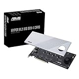
- Supports 4 NVMe M. 2 (2242/2260/2280/22110) up to 256 Gbps in one card by utilizing PCIe 4. 0 bandwidth
- PCIE 4. 0 X16 Interface with server-grade (low loss) PCB material, compatible with PCI express x8 and x16 slots
- Supports 14W power consumption SSDs for next gen latest drives
- Stylish heatsink and integrated blower style fan prevent M. 2 throttling
How to choose a card or power-management implementation
Compare candidates against the intended workload and platform, not just a headline power figure. Check these factors before enabling deeper power management or selecting a card:
What’s actually slowing this PC down?
Pick the symptom - the matching free tool is one click away.
- Power delivery: Confirm the supported slot and auxiliary-power class, connector requirements, and regulator capacity.
- Thermal margin: Check that the card and chassis can dissipate heat during sustained workload.
- Link behavior: Verify ASPM support, relevant L0s/L1 behavior, and exit latency for the design.
- Device-state and wake support: Establish which D-states the endpoint supports, whether D3cold is possible, and what auxiliary power or signaling wake requires.
- Platform compatibility: Validate BIOS/UEFI policy, ACPI methods, operating-system bus-driver behavior, and the endpoint driver together.
- Recovery and workload effects: Test suspend and resume, hot-plug if applicable, fault recovery, and performance impact under the workload that matters.
How to validate a power-saving configuration
- Establish a baseline. Measure the card or system under the target workload and during representative idle periods. Record operating conditions so comparisons are meaningful; do not treat a card’s maximum power class as its measured draw.
- Check delivery and cooling. Confirm the slot and auxiliary connectors meet the card’s requirements, then check temperatures during sustained workload.
- Validate link power management. Confirm the card, firmware, and operating system support the intended ASPM behavior. Compare idle power and workload responsiveness with it enabled and disabled.
- Validate runtime device states. Confirm endpoint-driver and bus-driver support, firmware and ACPI behavior, auxiliary-power requirements, wake signaling, and reset timing before relying on D3hot or D3cold.
- Exercise recovery paths. Test repeated suspend/resume and any applicable hot-plug or fault-recovery scenarios. Confirm the card returns to operation with configuration and interrupts restored, and check that wake behavior matches the system’s requirements.
Change one policy at a time and retain a known-good configuration. If deeper states cause failed resume, missing wake events, or device reinitialization problems, return to the last stable setting and investigate the driver, firmware, and platform path rather than assuming the card alone is at fault.
Best Value

- HIGH-PERFORMANCE USB CARD: Upgrade or expand a desktop/server's USB connectivity by adding four external USB Type-C 10Gbps ports and one internal USB Type-A 10Gbps port via a single PCI Express x4 connection
- FAST DATA TRANSFER: ASM3142 controller supports USB 3.2 transfer speeds of up to 10Gbps; Ideal for transferring large files or editing high-resolution photos/videos on external storage devices
- OPTIONAL POWER: USB PCIe expansion card with SATA power supplies additional power to the USB ports (when motherboard power is insufficient), providing up to 5V 3A (15W) per USB Type-C port and 5V 1.5A (7.5W) on the USB Type-A port
- COMPATIBILITY: Drivers auto-install in most OS's including Windows 8 & up, macOS, and Linux; Works with all hardware platforms such as Intel, AMD, and Apple Silicon that have a PCI Express x4/x8/x16 slot; Does not support DP-Alt Mode/USB Power Delivery
- THE IT PRO'S CHOICE: Designed and built for IT Professionals, this 5-port USB-C PCIe Card is backed for 2-years, including free lifetime 24/5 multi-lingual technical assistance
Common misconceptions
- “Enable ASPM and the whole card will use less power.” ASPM reduces link power while the endpoint remains operational; it does not itself put the device into a D-state.
- “D3cold is just a deeper D3hot.” D3cold removes the device’s supply voltage, while D3hot remains software-accessible.
- “A lower power-state number tells me exact watts saved.” State names do not provide a universal consumption figure. Savings depend on implementation and workload.
- “If a device supports a state, the system can use it safely.” Reliable entry, wake, and recovery depend on driver, firmware, ACPI, auxiliary-power, and platform coordination.
Sources and scope
The standards and implementation guidance cited here are PCI-SIG’s Card Electromechanical Specification Revision 6.0 (2024) and runtime-D3 engineering change notice; Linux PCI power-management documentation; Microsoft’s PCI power-management guidance; AMD’s PCIe IP guide; and Intel’s PCIe power-management material. The specific state behavior, available settings, and wake support can differ by card, driver, firmware, operating system, and platform.
Quick Recap
Product prices and availability are accurate as of the date/time indicated and are subject to change. Any price and availability information displayed on Amazon at the time of purchase will apply.

