
What’s actually slowing this PC down?
Pick the symptom - the matching free tool is one click away.
iTechGuides is reader-supported. When you buy through links on our site, we may earn an affiliate commission. As an Amazon Associate I earn from qualifying purchases. Learn more
Choose a Picotest injector by measurement function first, then verify frequency, voltage, current, load and connection limits. The J2100A and J2101A are passive injection transformers, the J2111A is a legacy solid-state current-sink injector, the J2120A injects ripple into a DC supply line, and the J2130A applies DC bias during component-impedance measurements. They are complementary instruments, not interchangeable versions of one product.
Quick model selection
| Model | Injector type | Best-fit measurement | Published limits or distinguishing details |
|---|---|---|---|
| J2100A | Injection transformer | Low-frequency control-loop injection, including PFC work | Usable bandwidth 1 Hz–5 MHz; 5 Ω termination; 600 V/CAT II isolation (Picotest specification sheet). |
| J2101A | Injection transformer | Higher-frequency regulator-loop work | Usable bandwidth 10 Hz–45 MHz; 5 Ω termination; 600 V/CAT II isolation (Picotest specification sheet). |
| J2111A | Legacy solid-state current injector and sink | Small-signal load steps, output impedance, PSRR and reverse-transfer measurements | Legacy FAQ describes positive and negative sink paths with a ±0.7 V dead region; it cannot source current. Picotest’s current catalog lists J2111B, not J2111A. |
| J2120A | DC supply-line injector | PSRR and input-filter testing by modulating the source line | 10 Hz–10 MHz usable range; 5 A maximum continuous current; 50 VDC maximum input; minimum load 10 mA; cannot sink current. |
| J2130A | DC-bias injector | Impedance measurements on biased components | Intended for capacitors, diodes, small-signal BJTs, optocouplers and related devices; confirm the applicable bias and measurement limits in its documentation. |
The values in the table are published product or specification-sheet figures, not a substitute for the relevant manual, absolute-maximum ratings or a wiring review.
Understand the three injection methods
Injection transformers for loop-response work
J2100A and J2101A couple a test signal into a feedback or power path while providing galvanic isolation. This is the usual approach when a network analyzer must measure loop gain, phase margin or related control-loop behavior without directly connecting its source to the power rail. Their practical difference in the published data is bandwidth: select the J2100A when coverage down to 1 Hz matters and the J2101A when the test extends into the tens of megahertz.
Solid-state current injection and sinking
The J2111A is described in Picotest’s legacy FAQ as a current sink for small-signal load steps and measurements such as output impedance, PSRR and reverse transfer. A sink changes the load seen by the device under test; it is therefore different from a transformer that inserts a voltage signal in a loop. The legacy description includes separate positive and negative sink paths and a dead region around zero volts, and states that the instrument cannot source current.
#1 Best Overall

- Arbitrary Waveform Generator adopts large scale FPGA integrated circuit and high-speed MCU microprocessor. The internal circuit adopts the active crystal oscillator as the benchmark. So the signal stability is greatly strengthened.
- Using Dual-channel DDS signal and TTL electric level output to generate precise, stable, low distortion output signal. includes Sine wave, Square wave, Triangle wave, Saw toothwave, Pulse wave, white noise, user-defined waveform etc. each channel can be independently set the parameters.
- With linear sweep(Max. up to 999.9s) and logarithmic frequency sweep functions.Has a frequency measurement, period measurement, positive and negative pulse width measurement and counting function.
- Storage feature: You can store 99 groups instrument state parameters set by the user, can be called up to Reproduce.The frequency output of Sine wave can be up to 15MHz. 200MSa/s sampling rate. It has 60 positions for saving user-defined waveform. Waveform Length of each one is 2048 and vertical resolution is 14 bits
- This Signal Generator is the ideal instrument for electronic engineering, laboratories, production lines, teaching and scientific research.
Line injection on a DC input
The J2120A modulates the DC supply input of a converter or other device. That makes it the task-specific choice for input-filter characterization and PSRR measurements taken from the supply side. It is not a general replacement for a loop-injection transformer or a load-step current sink.
DC bias during component impedance testing
The J2130A adds controlled DC bias while an impedance analyzer measures a component. This matters when capacitance, inductance or semiconductor junction behavior changes with operating voltage. Picotest materials cite capacitors, diodes, small-signal BJTs and optocouplers, along with varactors and junction-capacitance work, as examples.
Rank #2
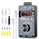
- 【2-in-1 Voltage & Current Generator】 Voltage Output: -10V~+10V, precision is 0.01V, current output: 0-22mA, precision is 0.01mA, rotate the encoder knob to adjust the output voltage and current, switchable and adjustable, can be calibrated. The encoder knob rotates one circle and has 20 pulses
- 【Multiple 4-Digit Display】 With 4 different types of digit displays and two decimal points, you can press the "Mode" button to switch the display mode between voltage and current. You can also follow the instructions to switch the 0-100 percent or 0-50 HZ display
- 【Different Power Supply Modes】 With a 1000mAh, 3.7V, built-in rechargeable battery embedded inside (charged via a micro USB port), it can be powered in various ways: micro USB-5V or external power DC 15-30V, each of which can make the signal generator work
- 【Safe to Use】 Output range: passive or active 0-22 mA, -10~+10V, the voltage output can be exactly 0.00V; output range and precision are programmable and adjustable. Output with short circuit protection, power supply has reverse connection protection, which is safe for you to use. The user can set 9 x fast signal output points, making it more convenient to do debugging
- 【Wide Application】 It can be used for PLC and panel debugging, device testing, frequency converters, flow valves, servo motor speed regulation, light dimmers, etc. With its small size, it is easy and convenient for you to carry it
What the bandwidth and ratings mean in practice
Frequency range is only one selection filter
A source that covers your highest frequency can still be unsuitable if its low-frequency limit, termination or coupling method does not fit the test. For example, the J2101A’s upper-frequency coverage favors fast regulator behavior, while the J2100A reaches lower frequencies for slower control dynamics. The analyzer, cable set, injection resistor or transformer connection and the device under test can reduce the usable range further.
Quick wins for a faster PC:
Repair Windows errors before they cause bigger problemsFix Now →Fix the driver behind crashes, sound loss and screen glitchesFind Drivers →Check voltage, current and load together
For the J2120A, the published 5 A figure is a maximum continuous current and the 50 VDC figure is a maximum input rating; neither describes a recommended operating point for every setup. The stated 10 mA minimum load also means an essentially open circuit is outside the documented operating envelope. Because the unit cannot sink current, a test in which the injector must absorb energy requires a different arrangement.
Rank #3

- 70MHz Dual Channel Arbitrary Waveform Generator:Generate precise signals with dual-channel output, 70MHz frequency range, and 300MSa/s sample rate, perfect for lab and engineering applications.
- High-Resolution 3.6” LCD Display:Enjoy crystal-clear waveform visualization, intuitive menu navigation, and real-time status monitoring, making waveform editing more convenient.
- 150 Built-in Arbitrary Waveforms:Choose from 5 standard waveforms (Sine, Square, Pulse, Ramp, Noise) and 150 built-in waveforms to meet diverse testing needs.
- Supports AM/FM/PM/FSK Modulation & PC Control:Equipped with multiple modulation modes, sweep/burst functions, and remote control via PC software, perfect for advanced experiments.
- Ultra-Thin & Portable Design:Lightweight compact body, quick-access shortcut keys, and easy operation, ideal for on-the-go engineers, students, and lab professionals.
Isolation and termination are setup constraints
The J2100A and J2101A specification sheet lists 5 Ω termination and 600 V/CAT II isolation. Treat those as instrument ratings, not permission to exceed the voltage, energy, creepage or category limits of the complete fixture. Probe grounds, analyzer outputs and the converter’s protective-earth arrangement must be reviewed as one system.
The J2111A revision issue
J2111A information appears in Picotest’s legacy FAQ, while the current Picotest catalog and current manual identify J2111B. Do not assume that the A-model sink behavior, limits, connectors or accessories apply to the B revision. If a listing or used instrument is marked J2111A, obtain the manual for that exact revision and compare its ratings before connecting it to a live power converter. Availability of the A revision is not established by the current catalog.
Rank #4

- 【Precise Conversion of Various Signal Types】 The 4-20ma signal generator is upgraded to support switching various signal modes available under different signal types: mA Current Signal (0 to 24 mA, precision 0.01mA), V Voltage Signal (0 to 24V, 0.01V), XMT Passive Current Signal (0 to 24mA, precision 0.01mA), Hz Pulse Signal (Frequency Output 0 to 9999 Hz, precision 5 digits). The input signal can be converted into an output signal among different physical quantities
- 【2.4 Inch TFT Colorful Screen】 Designed with an adjustable pressing button backlight and a high-definition 240*320 TFT color LCD screen, it makes the signal generator kit for PLC testing easier for users to operate at night and during the day
- 【Built-in 3000 mAh USB Rechargeable】 With a 3000 mAh 3.7V built-in USB rechargeable battery embedded inside (charged via a micro 5V USB port), the function generator can be fully charged within 4-6 hours. Its working length of up to 26 hours allows for a longer working period
- 【Multiple Interfaces to Choose】 Main interface programmable output. Input waveform interface: switchable input current graph display, input voltage graph display. VCA conversion interface: switchable voltage to active current, voltage to passive current, current to voltage. Automatic interface: automatic mode can be set for single ascent, single drop, and loop. PWM interface: Output PWM signal, voltage, frequency, and duty cycle can be set
- 【Programmable Output】 The 4-20 ma signal generator has the output function of auto, continuously changes the size according to the set parameters, and chooses three modes: monotonous rise, monotonous fall, and cycle
How to choose an injector for a real test
- Name the measured quantity. Use a transformer for feedback-loop injection, a current sink for load-step or output-impedance work, a line injector for supply-side PSRR and input-filter tests, or a DC-bias injector for component impedance under bias.
- Write the complete operating envelope. Record the lowest and highest frequency, DC voltage, AC perturbation, steady and transient current, minimum load and whether the injector must source, sink or remain isolated.
- Match the model’s published envelope. Compare those requirements with the table and the model-specific manual. Do not use a family-wide assumption for bandwidth or maximum voltage.
- Check the physical insertion point. Confirm where the instrument enters the feedback path, supply line, load path or component fixture; identify return-current paths and any required termination or bias network.
- Validate analyzer and fixture limits. Include generator amplitude, input impedance, cable ratings, probe category, connector current and thermal dissipation in the safety review.
- Run a low-level verification first. Start with a small perturbation, confirm the expected DC operating point and look for clipping, unexpected bias shifts, oscillation or excessive heating before increasing amplitude or bandwidth.
Why DC bias can change component results
Impedance measured at zero bias may not represent the component in its circuit. Picotest’s 2024 signal-injector brochure gives an X5R capacitor example, stating that such capacitors can lose up to 60% of their value at rated voltage. That is a manufacturer example for X5R behavior, not a universal loss figure for every capacitor or every voltage. The J2130A is relevant when the design question is the component’s impedance at its actual DC operating point.
Recommended Free Tools
Quick Recap
Best Value

- 【Upgraded Signal Stability】Seesii Dual-channel DDS arbitrary waveform generator adopts large-scale FPGA integrated circuit and high-speed MCU microprocessor. The internal circuit adopts an active crystal oscillator as a benchmark. So the signal stability is greatly strengthened
- 【Storage And Custom】 You can store 99 groups of instrument state parameters set by the user, which can be called up to Reproduce. The frequency output of a Sine wave can be up to 15MHz. 200MSa/s sampling rate. It has 60 positions for saving user-defined waveforms. In addition, it has a very good software package that allows you to create your waves and frequency combinations. After you save them, you can disconnect the unit from the computer and use them for any applications you wish
- 【High Precise】 Using Dual-channel DDS signal and TTL electric level output to generate a precise, stable, low distortion output signal. Includes Sine wave, Square wave, Triangle wave, Sawtooth wave, Pulse wave, white noise, user-defined waveform, etc. Each channel can be independently set the parameters. The duty cycle of each channel can be adjusted separately. Precision can be 0.1%
- 【Frequency Meter】With linear sweep(Max. up to 999.9s) and logarithmic frequency sweep functions.Has a frequency measurement, period measurement, positive and negative pulse width measurement, and counting function. The settings allow you to enter up to 20volts
- 【Lightweight Compact and Portable】With an intuitive control panel, you can easy to control. This Signal Generator is the ideal instrument for electronic engineering, laboratories, production lines, teaching, and scientific research. This is an important tool for both experts and newcomers
Common selection mistakes
- Buying by model number alone: similar names do not mean similar injection mechanisms.
- Using a transformer for a line-PSRR test: supply-line modulation calls for the line-injector topology and its current and voltage checks.
- Assuming a current injector can both source and sink: the J2111A legacy description and J2120A documentation identify one-way limitations.
- Ignoring minimum load: the J2120A’s documented minimum load is part of its operating envelope.
- Mixing J2111A and J2111B specifications: verify the exact revision’s manual.
- Reading bandwidth as guaranteed fixture performance: cables, terminations, bias networks and the device under test determine the result you actually obtain.
Bottom line for each model
- Pick J2100A when isolated transformer injection and coverage from 1 Hz through 5 MHz fit the loop test.
- Pick J2101A when the same transformer approach is needed into the higher-frequency range published for that model.
- Investigate J2111A carefully only when a legacy current-sink instrument is specifically required; confirm whether the available unit is actually the current J2111B revision.
- Pick J2120A for DC supply-line modulation in PSRR or input-filter measurements, provided its current, voltage and minimum-load limits fit.
- Pick J2130A when the measurement requires controlled DC bias on a component or semiconductor during impedance characterization.
Product prices and availability are accurate as of the date/time indicated and are subject to change. Any price and availability information displayed on Amazon at the time of purchase will apply.

