
iTechGuides is reader-supported. When you buy through links on our site, we may earn an affiliate commission. As an Amazon Associate I earn from qualifying purchases. Learn more
An open source high power EV motor controller is not one universal product. VESC is the strongest general-purpose open firmware ecosystem; OpenInverter is usually the better starting point for salvaged high-voltage automotive inverters; and ODrive is mainly a low-voltage robotics and servo platform. None automatically becomes a road-ready, safety-certified traction inverter.
The right choice depends on battery voltage, maximum charged voltage, battery and phase current, motor type, cooling, regeneration, position-sensor interface, and the amount of vehicle integration you are prepared to develop. A controller that can spin a motor on a bench is not necessarily suitable for a road car.
Key takeaways
- VESC offers the broadest open-source motor-control ecosystem, with GPLv3 firmware and published reference hardware under CC BY-SA 4.0.
- OpenInverter is more relevant to experienced builders using salvaged Toyota, Nissan, Tesla, BMW, or other automotive motors and inverters.
- Current-generation ODrive products are limited to 58 V for Pro, 50 V for S1, and 30 V for Micro, so they are not direct controllers for typical 96–400 V EV battery packs.
- Battery current, phase current, peak current, and continuous current are different measurements and cannot be compared without voltage, duration, and cooling conditions.
- Regenerative braking can raise the DC bus above the battery voltage, so the battery, brake resistor, or another clamp must safely absorb returned energy.
- For a road-going or production vehicle, a commercial traction inverter is generally the more defensible choice when validation, support, fault handling, and compliance matter more than firmware access.
What is the best open source high power EV motor controller?
VESC is the best general starting point for an open, modifiable motor-controller ecosystem. VESC is especially attractive for electric motorcycles, karts, boats, light vehicles, test benches, and custom traction systems where the selected board’s voltage, current, cooling, and sensor interfaces match the project.
OpenInverter is often the better route for a high-voltage EV conversion using a salvaged automotive drive unit. OpenInverter is oriented toward automotive inverter control, vehicle-specific parameters, CAN integration, and replacement control boards rather than a universal hobby ESC.
#1 Best Overall

- 【Perfect Curtis 1268-5403 Replacement】Directly replaces the Curtis 2CN090 (Model 1268-5403) motor controller. A cost-effective and reliable solution to restore your golf cart's performance without the OEM price tag. Plug-and-play installation designed for seamless integration.
- 【Wide Compatibility for Star EV Carts】Specifically engineered for 2016 and newer Star EV models including: Classic 48-2, 48-4, 48-6 series (all +2 variants), Sport 2+2, 4+2, and Sport XPR. Please double-check your existing controller's part number (2CN090/1268-5403) and cart model before ordering to ensure a perfect fit.
- 【Enhanced 48V 400A Performance】Delivers robust 400-amp output for improved torque, smoother acceleration, and reliable hill-climbing power. Maintains optimal speed control and protects your motor with advanced thermal and overload management.
- 【0-5K Ohm Throttle Compatible】Works flawlessly with the standard 0-5K ohm potentiometer throttle input system used in these Star EV carts. Ensures precise speed control from a gentle crawl to full power.
- 【Built to Last & Backed by One Year Of After-Sales Service】Features high-quality components, corrosion-resistant connectors, and a durable aluminum housing. Every Star EV golf cart 48V controller comes with one year of comprehensive after-sales support. We stand behind our product with dedicated customer support to assist with your installation and questions.
ODrive is a useful alternative for low-voltage robotics, servo, and test-stand work, but it is not a general high-voltage EV traction answer. ODrive’s current documentation lists 58 V for ODrive Pro, 50 V for ODrive S1, and 30 V for ODrive Micro; those limits make the products unsuitable for direct connection to typical 96–400 V traction batteries. See the current ODrive documentation and product limits.
How do VESC, OpenInverter, ODrive, and commercial inverters compare?
| Option | Firmware openness | Hardware openness | Typical role | EV voltage suitability | Main advantage | Main limitation |
|---|---|---|---|---|---|---|
| VESC ecosystem | Open-source firmware under GPLv3 | Published reference hardware; commercial boards vary | BLDC/PMSM control, light traction, prototypes | Depends on the exact board | Mature ecosystem, configurable FOC, broad hardware support | Board ratings and thermal performance vary; peak-current marketing can mislead |
| OpenInverter | Community-driven open firmware and parameter resources | Depends on the particular project and power stage | Salvaged automotive motors and inverters | Often more relevant to high-voltage EV conversions | Automotive integration and vehicle-specific knowledge | Complex, hardware-specific, and not plug-and-play |
| ODrive | Mixed by hardware generation | Mixed by hardware generation | Robotics, servo axes, and motor test stands | Generally low-voltage | Convenient development workflow and position control | Not a direct high-voltage traction solution; current-generation hardware is not fully open |
| Commercial traction inverter | Usually proprietary | Usually proprietary | Road-vehicle and production deployment | Often available for high-voltage systems | Support, documentation, validation, and integration options | Higher cost and limited modification |
The table compares categories, not interchangeable products. “VESC-compatible” does not necessarily mean official VESC hardware. A third-party board may use compatible firmware while changing the power stage, components, current sensors, voltage limits, thermal design, connectors, and firmware target.
What does “high power” mean for an EV motor controller?
“High power” is not a standardized controller rating. Start with the battery’s nominal voltage, maximum charged voltage, continuous and peak current, motor phase current, peak duration, cooling system, and regeneration requirement.
What’s actually slowing this PC down?
Pick the symptom - the matching free tool is one click away.
The approximate electrical input relationship is:
PDC ≈ Vbattery × Ibattery
| Battery condition | Approximate electrical input | What the figure does not prove |
|---|---|---|
| 48 V × 100 A | Approximately 4.8 kW | It does not guarantee 4.8 kW of mechanical output |
| 96 V × 200 A | Approximately 19.2 kW | It does not specify phase current, duration, or thermal capability |
| 360 V × 200 A | Approximately 72 kW | It does not account for inverter loss, motor loss, voltage sag, or transient limits |
Actual mechanical output is lower and depends on inverter losses, motor efficiency, battery voltage sag, switching losses, motor temperature, inverter temperature, and the duration of the load. A controller advertised as “300 A” may mean battery-side current, phase current, a brief peak, a software ceiling, or a value achievable only with specified cooling.
Before comparing two controllers, record these values separately:
- Battery nominal voltage and maximum charged voltage
- Battery continuous and peak current
- Motor phase current and whether the figure is peak, RMS, or instantaneous
- Peak-current duration and duty cycle
- Motor Kv or voltage constant, maximum speed, and pole-pair count
- Cooling-plate temperature, coolant flow, fan conditions, and ambient temperature
- Regenerative-braking power and the battery’s maximum charge-current acceptance
- Hall, encoder, SPI encoder, resolver, or sensorless position feedback
- Required torque, speed, position, throttle, CAN, and BMS-control modes
Is VESC genuinely open source?
VESC is meaningfully open at the firmware and reference-hardware level, but the licenses are different. The VESC firmware repository describes open-source motor-controller firmware and identifies GPLv3 licensing. The VESC hardware repository publishes reference hardware under Creative Commons Attribution-ShareAlike 4.0.
Those licenses do not mean that every commercial VESC-derived controller is identical to the reference design. A buyer must inspect the exact board’s schematics, bill of materials, PCB files, firmware target, gate driver, current sensors, voltage range, thermal path, and vendor documentation.
Do these 3 things before closing this tab:
1Repair Windows errors before they cause bigger problems2Scan for outdated or missing drivers - takes under a minute3Clear out junk files and repair common Windows errors“Open source” can describe several different things:
| Layer | Question to ask |
|---|---|
| Firmware | Can the source be inspected, modified, built, and redistributed under its license? |
| Schematics | Are the control, sensing, gate-driver, and protection circuits published? |
| PCB design | Are board layouts and manufacturing files available? |
| Bill of materials | Can components and substitutes be identified? |
| Mechanical design | Are enclosures, heatsinks, and mounting files documented? |
| Communications | Are CAN, UART, USB, and configuration protocols documented? |
| Redistribution | Can modified firmware or hardware be shared under the applicable license? |
| Branding | Are trademark and official-distribution rules separate from the open-source license? |
The VESC Tool source repository distinguishes publicly available source from official binary distribution and also documents the separate VESC Project branding and distribution context.
What motors can VESC and OpenInverter control?
VESC is primarily associated with brushless DC and permanent-magnet synchronous motors using field-oriented control, including surface-permanent-magnet and interior-permanent-magnet designs. OpenInverter is more relevant when the motor is part of a salvaged automotive inverter and requires vehicle-specific position sensing, gate-drive behavior, CAN messages, and parameterization.
Potential motor categories include:
- BLDC motors
- Permanent-magnet synchronous motors
- Surface- and interior-permanent-magnet motors
- Hub motors and mid-drive motors
- Some induction-motor systems through suitable automotive inverter projects
- Some switched-reluctance systems through dedicated hardware and firmware
- Salvaged automotive drive units, where inverter and sensor compatibility must be established individually
No firmware package automatically supports every motor type, inverter topology, sensor interface, or power stage. A salvaged automotive motor may use a resolver or proprietary encoder interface rather than the Hall or incremental encoder input available on a hobby controller.
Quick wins for a faster PC:
Repair Windows errors before they cause bigger problemsFix Now →Scan for outdated or missing drivers - takes under a minuteDriver Scan →Why does field-oriented control matter?
Field-oriented control, or FOC, measures phase currents and rotor position, transforms the three-phase current into flux-producing and torque-producing components, and regulates those components with current loops. FOC can provide smooth torque, efficient operation, regenerative braking, and field weakening when the hardware and firmware support the required functions.
FOC does not make commissioning automatic. The controller needs correct motor parameters, pole-pair count, phase order, current-sensor scaling, rotor angle, direction, voltage limits, and current limits. An incorrect encoder angle, sensor calibration, or protection threshold can produce violent startup behavior or destroy the inverter.
For EV traction, ask whether the controller supports adequate current-sampling bandwidth, the required rotor-position sensor, field weakening, regenerative braking, thermal derating, overcurrent and overvoltage protection, BMS communication, CAN integration, and safe fault behavior. The OpenInverter parameter documentation illustrates the automotive-specific tuning burden with field-weakening parameters and inverter-heatsink temperature limits.
What hardware does a high-power EV controller require?
A high-power EV motor controller is a complete power-electronics system, not merely a microcontroller connected to three transistors.
- DC input stage: fuse, contactor or solid-state switching, precharge circuit, DC-link capacitors, voltage measurement, and a discharge path.
- Three-phase inverter: six MOSFETs, IGBTs, or SiC MOSFETs; high- and low-side gate drivers; suitable bootstrap or isolated supplies; current sensing; short-circuit protection; snubbers; and a layout designed for switching transients.
- Control electronics: MCU or DSP, PWM generation, ADC sampling, rotor-position interfaces, CAN, UART or USB, watchdogs, and fault logic.
- Thermal system: baseplate or heatsink, liquid cooling for serious continuous power, temperature sensors, thermal-interface materials, and software current derating.
- Vehicle integration: throttle plausibility, brake input, BMS limits, charger and contactor coordination, neutral and reverse logic, CAN messaging, isolation monitoring, fault shutdown, and an emergency disconnect.
An open controller can still require a separately engineered battery-management system, precharge network, contactors, cooling loop, enclosure, cabling, and vehicle safety system. Firmware openness does not certify the surrounding high-voltage architecture.
How does the VESC firmware workflow work?
The VESC firmware repository provides a reproducible build workflow, but building firmware is not the same as commissioning a traction system. The repository is available at github.com/vedderb/bldc.
git clone http://github.com/vedderb/bldc
cd bldc
make arm_sdk_install
make
make 100_250
Replace 100_250 with the exact supported target for the physical controller. The repository uses target-specific builds, and the output is placed in a directory such as:
Rank #2
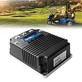
- 【EASY, PLUG-AND-PLAY INSTALLATION】Designed as a direct plug-and-play replacement. No complex wiring or modifications needed, Get your golf cart running like new with basic tools. It is suitable for confident DIYers. Just be sure you go over everything this is compatible with ahead of time as well as the measurements.
- 【ENHANCED 48V 400A PERFORMANCE】Experience smooth acceleration, consistent power output, and reliable hill-climbing ability. This 48-Volt, 400-Amp dc controller is engineered to the highest performance standards, ensuring your golf cart runs powerfully and efficiently, round after round. Part Number:(2CN090)
- 【WIDE COMPATIBILITY FOR STAR EV GOLF CARTS】This 48V DC golf cart speed controller is specifically designed for 2016 UP Star EV and Classic Custom golf carts. Ensures a perfect fit for Classic 48-2, Classic 48-2+2, Classic 48-4, Classic 48-4+2, Classic 48-6, Classic 48-6+2, Sport 2+2, Sport 4+2, and Sport XPR models with 0-5K throttle type. We recommend confirming your golf cart's model number before ordering to ensure compatibility!
- 【PERFECT CURTIS 1268-5403 REPLACEMENT】Designed as a direct replacement for the Curtis 1268-5403 motor controllers. Offers the reliable performance and seamless integration without the high cost of the OEM part. Stop the guesswork, this is the right fit for your needs.
- 【EXCELLENT AFTER-SALES SERVICE】CIRFREETION not only focuses on the design and development of golf cart controllers but also ensures the quality and performance of its products. Every STAR EV golf carts dc motor controller comes with a ONE-YEAR after-sales service. For any product-related questions, please do not hesitate to contact us.
bldc/builds/100_250/Flashing can be performed through an SWD debugger after programming the bootloader or by uploading custom firmware through VESC Tool over USB. The repository warns against removing power or USB during upload and instructs users to wait approximately 10 seconds after upload completion before disconnecting. A failed upload may require an SWD debugger for recovery.
Never flash a valid image built for one board target onto a different board merely because both boards are described as VESC-compatible. Incorrect pin mappings, gate-driver behavior, current scaling, or voltage measurement can damage the controller.
When is OpenInverter the better choice?
OpenInverter is the stronger candidate when the project uses a salvaged OEM motor and inverter and the builder is prepared for vehicle-specific development. The ecosystem includes work involving Toyota and Lexus hybrid components, Nissan Leaf systems, Tesla drive units, BMW systems, replacement control boards, firmware, and CAN-controlled EV conversions.
The OpenInverter parameter database includes motor, inverter, battery-voltage, vehicle-weight, driven-wheel, and tuning-goal fields. Those fields show that the project is aimed at complete vehicle configurations rather than isolated motor experiments.
OpenInverter’s advantages are automotive relevance, salvaged-drive-unit knowledge, community parameter sets, and the possibility of retaining an OEM power stage while replacing or augmenting its control electronics. The trade-off is complexity: the builder may need to understand resolver signals, gate-driver initialization, current sensing, DC-link behavior, CAN messages, thermal protection, and the original inverter’s fault assumptions.
A parameter file from another vehicle is a starting point, not a universal safe configuration. Battery voltage, motor speed, gear ratio, cooling, sensor scaling, current limits, and mechanical load can all differ. OpenInverter documentation warns that incorrect parameters can cause violent startup or immediate power-stage damage when a high-energy battery is connected.
Why is ODrive mainly a boundary case for EV traction?
ODrive is well suited to robotics, servo axes, position-control applications, low-voltage prototypes, and motor test stands, but its current products do not directly answer the high-voltage EV traction requirement.
| ODrive product | Documented voltage limit | Typical implication |
|---|---|---|
| ODrive Pro | 58 V | Low-voltage systems, not a direct 96–400 V traction-battery controller |
| ODrive S1 | 50 V | Low-voltage motor-control applications |
| ODrive Micro | 30 V | Lower-voltage embedded and compact applications |
ODrive documentation also states that versions after v3.5 are closed source regarding board files and schematics. That distinction matters: articles that describe every ODrive product as fully open source are too broad. See the ODrive specifications and source-status documentation.
The ODrive v3.6 specifications list 120 A peak motor current, with continuous-current capability depending on cooling. The same specification page gives different continuous-current figures for still air, fan cooling, and heavier fan cooling, demonstrating why peak current alone cannot establish continuous traction power.
The Tool Desk
Outbyte Driver Updater FREEScan for outdated or missing drivers - takes under a minuteDriver Scan →Outbyte PC Repair FREEClear out junk files and repair common Windows errorsFree Scan →ODrive Pro and Micro do not include built-in brake-resistor functionality according to the current documentation. A regenerative-braking application therefore needs a battery that can safely absorb returned energy or an appropriate external regeneration solution. The ODrive documentation should be checked for the exact hardware revision and braking architecture.
How should you choose between open and commercial controllers?
| Project | Most sensible starting point | Why | Important qualification |
|---|---|---|---|
| Low-voltage bench prototype | ODrive or a smaller VESC-derived board | Convenient development and accessible control interfaces | Check voltage, braking, current, and source-status limits for the exact board |
| E-bike, scooter, kart, or small boat | VESC-derived controller | Strong open ecosystem and configurable FOC | Verify continuous thermal performance rather than advertised peak current |
| Electric motorcycle or light vehicle | Appropriately rated VESC-derived hardware | CAN, configurable control, and broad community experience | Board voltage, phase current, cooling, and enclosure design are decisive |
| High-voltage salvaged EV drive unit | OpenInverter-related project | Better alignment with OEM inverter, sensor, and CAN requirements | Compatibility is vehicle- and inverter-specific |
| High-voltage road-car conversion | Commercial traction inverter or validated automotive platform | Reduces development and validation burden | Open-source projects can still be useful for research and integration work |
| Production or safety-critical vehicle | Commercial automotive solution | Support, traceability, environmental validation, and fault-handling evidence | Legal and technical requirements vary by jurisdiction and vehicle |
Choose VESC when firmware modification and ecosystem breadth are the priority. Choose OpenInverter when the motor and inverter are salvaged automotive hardware. Choose ODrive when low-voltage servo behavior matters more than EV traction voltage. Choose a commercial inverter when development time, support, reliability, and validation outweigh the benefits of open modification.
How should a serious EV controller be commissioned?
Commissioning should proceed from a mechanically restrained, low-energy test toward loaded and vehicle testing. Do not begin by connecting a fully charged high-voltage battery and applying throttle.
Stage 1: Prepare the mechanical and electrical system
- Secure the motor so unexpected torque cannot move the assembly or injure anyone.
- Remove the mechanical load or use a safe, low-energy test arrangement.
- Measure motor phase resistance and verify insulation.
- Identify Hall, encoder, or resolver wiring and confirm the interface voltage and signal type.
- Verify battery and controller polarity.
- Install the correct fuse, contactors, and precharge circuit.
- Confirm that the battery can accept regenerative current or that an external brake-resistor or regeneration-clamp path is correctly sized.
ODrive’s setup documentation emphasizes considering what happens when the motor starts immediately after power is applied and recommends connecting the power source before enabling the motor where possible. The ODrive setup guidance is useful as a general commissioning reminder even when the final controller is different.
Outdated Drivers Are Slowing You Down
One free scan finds every outdated or missing driver and matches the right update for your exact hardware.Free scan · exact hardware matchWindows Errors? Fix Them Before They Spread
Repair common Windows errors and clear accumulated junk for a smoother, more stable PC - no reinstall needed.Free scan · no reinstallStage 2: Use a low-voltage, current-limited test
- Use a current-limited supply when the controller and motor permit it.
- Set conservative motor-current and battery/DC-current limits.
- Verify current-sensor readings before applying meaningful torque.
- Confirm phase order, motor direction, pole-pair count, and sensor polarity.
- Run motor identification or calibration at a conservative limit.
- Check the reported encoder angle and physical direction.
ODrive’s setup guide recommends starting with a relatively weak current limit and distinguishes a soft current limit from a higher hard-fault limit. The principle applies broadly: software limits should be conservative during first motion, while independent hardware protection must remain available.
Stage 3: Test no-load operation
- Increase speed gradually.
- Monitor motor and inverter temperatures.
- Check current waveform, vibration, and acoustic behavior.
- Confirm that regenerative braking does not overvoltage the DC bus.
- Test fault shutdown, restart behavior, and loss-of-sensor behavior.
- Confirm that commanded direction matches physical direction.
Stage 4: Test under load
- Add mechanical load incrementally.
- Log DC voltage, DC current, phase current, speed, temperatures, and fault codes.
- Test the intended continuous duty cycle rather than only a short acceleration.
- Test acceleration and regenerative braking separately.
- Validate battery, contactor, fuse, cooling, and BMS behavior.
Stage 5: Integrate the vehicle
- Add throttle plausibility checks and brake override.
- Implement neutral, reverse, and direction interlocks.
- Validate precharge and contactor sequencing.
- Define behavior when CAN messages stop or contain invalid data.
- Test encoder or resolver disconnection and implausible-signal faults.
- Test power-off and emergency-stop behavior.
- Do not rely on software as the only high-voltage safety mechanism.
Why are thermal ratings and current terminology so important?
Continuous power is primarily a thermal question. Semiconductor conduction loss, switching loss, PWM frequency, bus voltage, current, heatsink temperature, coolant flow, PCB copper, busbar design, enclosure airflow, ambient temperature, and derating strategy all affect the sustainable rating.
Battery current and phase current are not interchangeable. A controller can deliver high phase current at low speed while drawing a different battery current, and a phase-current peak may last only milliseconds or seconds. Ask every vendor for the measurement domain, waveform or RMS definition, duration, duty cycle, cooling conditions, and temperature at which derating begins.
ODrive’s v3.6 specification is a useful example of the principle: the specification lists 120 A peak motor current but gives different continuous-current figures depending on whether the heatsink is in still air, fan cooled, or heavily fan cooled. Those figures belong to that specific board and should not be generalized to VESC or other hardware.
Recommended Free Tools
The maximum controller voltage is also not the same as the battery’s nominal voltage. The fully charged pack, wiring inductance, switching overshoot, and regenerative-braking event must all remain below the controller’s absolute limits with appropriate design margin.
Rank #3
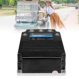
- 【PERFECT CURTIS 1268-5403 REPLACEMENT】Designed as a direct replacement for the Curtis 1268-5403 motor controllers. Offers the reliable performance and seamless integration without the high cost of the OEM part. Stop the guesswork, this is the right fit for your needs.
- 【WIDE COMPATIBILITY FOR STAR EV GOLF CARTS】This 48V DC golf cart speed controller is specifically designed for 2016 and newer Star EV and Classic Custom golf carts. Ensures a perfect fit for Classic 48-2, Classic 48-2+2, Classic 48-4, Classic 48-4+2, Classic 48-6, Classic 48-6+2, Sport 2+2, Sport 4+2, and Sport XPR models with 0-5k throttle type. We recommend confirming your golf cart's model number before ordering to ensure compatibility!
- 【ENHANCED 48V 400A PERFORMANCE】Experience smooth acceleration, consistent power output, and reliable hill-climbing ability. This 48-Volt, 400-Amp dc controller is engineered to the highest performance standards, ensuring your golf cart runs powerfully and efficiently, round after round. Part Number:(2CN090)
- 【EASY, PLUG-AND-PLAY INSTALLATION】Designed as a direct plug-and-play replacement. No complex wiring or modifications needed, Get your golf cart running like new with basic tools. It is suitable for confident DIYers. Just be sure you go over everything this is compatible with ahead of time as well as the measurements.
- 【EXCELLENT AFTER-SALES SERVICE】CIRFREETION not only focuses on the design and development of golf cart controllers but also ensures the quality and performance of its products. Every STAR EV golf carts dc motor controller comes with a ONE-YEAR after-sales service. For any product-related questions, please do not hesitate to contact us.
What happens during regenerative braking?
Regenerative braking returns energy from the motor to the DC bus and can raise bus voltage above the battery voltage. The battery must accept the charge current, or a correctly engineered brake resistor, active clamp, or other regeneration path must absorb the energy.
Failure modes include a BMS opening the contactor while regeneration continues, an undersized brake resistor, excessive negative-current limits, long battery cables, insufficient DC-link capacitance, and DC-bus overvoltage. ODrive’s component-selection guidance warns that active braking can increase controller voltage and recommends leaving voltage margin below the controller’s maximum rating. ODrive’s hardware configuration documentation also discusses positive and negative DC-current limits, overvoltage limits, and regenerated current.
Regeneration must be tested independently from acceleration. A controller that accelerates correctly may still fail when the motor decelerates, the battery is full, or the BMS refuses charge current.
Free tools Windows power users keep installed
One-click scans. No signup required.
What are the most common failure modes?
| Symptom | Likely causes | First checks |
|---|---|---|
| Motor spins backward or starts violently | Wrong phase order, Hall or encoder sequence, encoder angle, pole-pair count, current scaling, direction, or excessive startup current | Return to low-voltage current-limited commissioning and verify sensor calibration and motor parameters |
| Controller fails during regeneration | Battery cannot accept charge, BMS opens, DC-bus overvoltage, missing or undersized brake resistor, cable inductance, or incorrect negative-current limit | Log DC-bus voltage and regenerative current; verify the energy-absorption path before repeating the test |
| Controller overheats during “rated” operation | Peak rating treated as continuous, inadequate heatsink or coolant flow, switching losses, high ambient temperature, or missing derating | Compare actual duty cycle and temperatures with the exact board’s thermal specification |
| Firmware behaves incorrectly after flashing | Firmware target does not match the physical board revision | Confirm the board target, pin mapping, current scaling, voltage measurement, and recovery method |
| Salvaged inverter does not communicate | Incorrect CAN messages, proprietary resolver interface, gate-driver initialization, sensor scaling, or DC-link assumptions | Identify the exact inverter revision and document every required interface before applying high voltage |
OpenInverter’s parameter documentation specifically warns that incorrect settings can cause violent startup or immediate power-stage damage on a high-energy battery. Treat community configurations as engineering starting points, not certified universal settings.
Does open source make an EV controller road legal or automotive safe?
No. Open-source firmware and hardware can improve inspectability, repairability, customization, and education, but they do not by themselves provide functional-safety evidence, EMC compliance, production traceability, automotive environmental qualification, fail-operational behavior, warranty, regulatory approval, or road legality.
Road-vehicle requirements vary by jurisdiction and may involve vehicle inspection, braking, electrical safety, isolation, electromagnetic compatibility, and functional-safety obligations. A controller that works in a community build is not automatically approved for public-road use.
What does the project really cost?
The purchase price of the controller is only one part of an open EV traction project. The total effort can include a high-voltage battery and BMS, contactors and precharge, cooling, motor sensors, high-voltage cables and connectors, a CAN gateway, enclosure, instrumentation, spare semiconductors or controller boards, and failed prototypes.
Commercial pricing is highly variable for VESC-derived hardware and depends on voltage, current, enclosure, connectors, cooling, and vendor. OpenInverter is primarily a community and project resource rather than one standardized retail product line, so availability and support depend on the exact inverter, control board, supplier, and vehicle. Current ODrive prices should be checked on the official vendor site rather than assumed from a generic comparison; the permitted research does not verify current prices.
The economic decision is therefore not simply “open source versus expensive.” Compare the cost of development time, test equipment, failures, and validation with the price of a supported commercial traction inverter. Open hardware is most valuable when modification, repairability, or learning is worth the additional engineering work.
Recommended decision
For the broadest open-source ecosystem, start with VESC and select a specific board only after verifying its maximum charged-battery voltage, continuous battery and phase current, cooling, regenerative-braking behavior, sensor inputs, CAN implementation, and firmware target.
For a salvaged high-voltage automotive drive unit, investigate OpenInverter-related projects and the exact motor, inverter, sensor, CAN, gate-drive, and thermal documentation for that system.
For a low-voltage robot, servo axis, or laboratory test stand, ODrive can be a practical choice, provided the exact product’s voltage, current, braking, and source-status limits fit the application.
For a road-going or production vehicle, favor a commercial automotive traction inverter or a thoroughly validated development platform when safety, support, reliability, compliance, and deployment time are more important than access to modifiable source code.
Frequently Asked Questions
Can a VESC controller run a 400 V EV battery?
A VESC controller can be used only when the exact board is designed and rated for the battery’s maximum charged voltage, including transient and regenerative events. The VESC ecosystem contains many different boards, so firmware compatibility alone does not establish 400 V capability.
Is OpenInverter a universal EV motor controller?
OpenInverter is not a universal plug-and-play controller; it is an open community automotive-inverter platform whose compatibility depends on the specific motor, inverter, sensors, power stage, CAN messages, cooling system, and parameters.
Recommended Free Tools
Is ODrive fully open source?
ODrive is not uniformly fully open source across product generations. ODrive documentation states that versions after v3.5 are closed source regarding board files and schematics, even though software and documentation may be publicly available.
What is the difference between battery current and phase current?
Battery current is current flowing between the battery and the inverter, while phase current flows between the inverter and motor phases. Phase current can be much higher than battery current in some operating conditions, so a peak phase-current rating cannot be used as a battery-current or continuous-power rating.
Can regenerative braking damage an EV motor controller?
Regenerative braking can damage an EV motor controller if returned energy raises the DC bus above its safe limit. The battery, brake resistor, active clamp, or another approved energy-absorption path must accept the regenerated current, including cases where the BMS is full or disconnects the pack.
The Bottom Line
Bottom line: VESC is the best open-source general-purpose starting point, OpenInverter is the more relevant path for salvaged high-voltage automotive inverters, and ODrive is mainly a low-voltage robotics and servo alternative. For a road-going EV, treat any open controller as a development platform until the complete inverter, battery, cooling, fault handling, isolation, and vehicle integration have been validated.
Quick Recap
Product prices and availability are accurate as of the date/time indicated and are subject to change. Any price and availability information displayed on Amazon at the time of purchase will apply.

