
Quick wins for a faster PC:
Clear out junk files and repair common Windows errorsFree Scan →Fix the driver behind crashes, sound loss and screen glitchesFind Drivers →Repair Windows errors before they cause bigger problemsFix Now →iTechGuides is reader-supported. When you buy through links on our site, we may earn an affiliate commission. As an Amazon Associate I earn from qualifying purchases. Learn more
A backward-connected LED usually stays off because it blocks current in reverse. That does not make reverse connection safe: excessive reverse voltage can force the LED into breakdown and permanently damage it. Many conventional indicator LEDs specify about 5 V reverse voltage, but that is not universal. Check the exact datasheet, limit forward current with a resistor or constant-current driver, and use a separate diode, MOSFET, bridge, or protection controller when the circuit must survive a reversed supply.
Reverse polarity, reverse voltage, and reverse-polarity protection
Reverse polarity means the supply connections are swapped: the positive supply is connected to circuit ground and the negative supply to the circuit’s positive input. Reverse voltage is the voltage across one component in its non-conducting direction. Reverse-polarity protection is a circuit that prevents a reversed supply from damaging the load. A reverse-polarity indicator deliberately lights when the supply is connected backward; it is not, by itself, protection.
Correct:  + supply → circuit V+     − supply → circuit GND
Reversed: + supply → circuit GND     − supply → circuit V+
How to identify an LED’s polarity
For a new through-hole LED, the longer lead is usually the anode and the shorter lead the cathode. The flat package edge commonly marks the cathode, and the larger internal metal electrode is often the cathode. On a PCB, look for a diode-symbol bar, a flat-edge marking, or a “K” label.
Recommended Free Tools
These conventions vary by package and manufacturer. SMD LEDs especially require the datasheet, package drawing, or PCB documentation. In the circuit symbol, the bar is the cathode:
#1 Best Overall

- 🔴 Red VF:1.9-2.1 IF 20mA 70pcs 🟢 Green VF:3.0-3.2 IF 20mA 70pcs 🟡 Yellow VF:1.9-2.1 IF 20mA 70pcs 🔵 Blue VF:3.0-3.2 IF 20mA 70pcs 🟠 Orange VF:1.9-2.1 IF 20mA 70pcs ⚪️ White VF:3.0-3.2 IF 20mA 70pcs
- Versatile Multi-Color Options – A 5 mm LED assortment (white, red, yellow, orange, green, blue) gives you a full range of multi color lights for electronic projects, kits, and circuit experiments. Perfect for Christmas repair, hobby crafts, nano bright bobber lighting, or electronic replacement bulbs.
- Compact and Easy to Use – These small lamp diodes are standard through-hole components that fit breadboards and PCBs, making them ideal for DIY projects, kits, and classroom experiments. The simple mm light parts are plug-and-play for beginners and advanced makers.
- Low Power, High Brightness – Each mini DC lighting diode operates at low power volt while still providing super bright leds. Whether you need a micro craft lamp, bulk replacement bulbs, or individual pcs lights, they deliver efficient illumination for extended use.
- Durable & Long Life – These leds and emitting diodes are rugged electronic components, resistant to vibration and long-lasting compared to traditional leuchtstoffröhre bulbs. Excellent for kits and projects that require reliable lighting parts.
Anode ──|>|── Cathode
             bar
What happens when an LED is connected backward?
At a modest reverse voltage
The LED normally remains dark, with only a small leakage current. If it is merely a parallel indicator, the rest of the circuit may continue to operate.
At excessive reverse voltage
The LED junction can enter reverse breakdown. Reverse current then rises sharply, causing immediate damage or degradation over time. A failed LED may become open-circuit, short-circuit, dim, intermittent, or unusually leaky.
Kingbright catalog examples list a 5 V reverse-voltage rating for several conventional indicator families (Kingbright catalog; Kingbright electrical data). This is a common value, not a universal LED rule. Lumileds states that several LUXEON families are not designed for reverse bias; some datasheets permit only tightly limited reverse-voltage transients with specified current and duration (LUXEON 3030, LUXEON 2835 Architectural, LUXEON Q).
A one-time accidental reversal that appears harmless is not proof of safe continuous operation. Damage can be electrical or gradual without visible changes.
Rank #2

- Dual-Size Versatility: Each color (White/Red/Blue/Green/Yellow) includes 20pcs 5mm LEDs and 40pcs 3mm LEDs, totaling 300pcs. Perfect for projects requiring flexibility in size and brightness.
- Precise Technical Specs: Forward Voltage: Red/Yellow 2.0-2.2V; Blue/Green/White 3.0-3.2V.
- Wide Application: Ideal for DIY electronics, Arduino/Raspberry Pi projects, PCB circuits, car decorations, science experiments and holiday lights.
- Organized Storage: Color-coded and size-separated in a labeled plastic case for easy access and protection against damage.
- Premium Quality: High-conductivity silver-plated pins and durable materials ensure long-lasting performance.
Why a discrete LED needs a resistor
An LED is driven by controlling current, not by applying a fixed voltage directly. For a simple series circuit:
R = (VS − VF) / IFVS: highest expected supply voltageVF: LED forward voltage at the intended currentIF: desired forward current in amperes
Example: with a 5 V supply, a 2.0 V LED and 10 mA target current, R = (5 − 2.0) / 0.010 = 300 Ω. Choose the next common value, such as 330 Ω. At 10 mA, that resistor dissipates about I²R = 0.033 W, so a 0.125 W or 0.25 W part normally has useful margin. Use the datasheet’s forward-voltage range, supply tolerance, temperature, and worst-case power—not only a nominal color-based voltage. High-power LEDs generally need a constant-current driver.
Can a backward LED damage the power supply?
Usually not when the LED is in series with a correctly sized resistor. The resistor limits current in either direction. Risk rises when the LED is directly across a source, when it breaks down, or when another low-impedance path allows substantial current. A battery or automotive supply can deliver enough current to destroy an LED, wiring, or a protection diode.
Windows Errors? Fix Them Before They Spread
Repair common Windows errors and clear accumulated junk for a smoother, more stable PC - no reinstall needed.Free scan · no reinstallOutdated Drivers Are Slowing You Down
One free scan finds every outdated or missing driver and matches the right update for your exact hardware.Free scan · exact hardware matchMethods for protecting a circuit from reverse polarity
| Method | Normal voltage loss | Complexity | Best fit | Main limitation |
|---|---|---|---|---|
| Series silicon diode | About one diode forward drop | Low | Low/moderate current, simple designs | Heat and lost voltage headroom |
| Series Schottky diode | Lower than silicon, at the cost of leakage | Low | Battery and low-voltage circuits | Voltage and temperature ratings must fit |
| Fused shunt diode | Almost none during normal operation | Low | Fused or current-limited sources | Can short an unfused battery |
| P-channel MOSFET | Low I²R loss when on |
Moderate | Higher-current, high-side protection | Body-diode orientation and gate limits matter |
| Ideal-diode controller with N-channel MOSFET | Very low when correctly designed | High | High current, automotive, low-loss designs | More parts and validation |
| Bridge rectifier | Two diode drops | Low | Inputs that may be connected either way | Often unsuitable for 3.3 V or 5 V rails |
| Protected indicator or module | Depends on product | Low installation effort | Panel equipment and prototypes | Ratings and availability are product-specific |
Series diode or Schottky diode
Place the diode in series with the positive input so it conducts with correct polarity and blocks a reversed supply. Diodes Incorporated describes series Schottky protection for LED flashlight circuits and the associated forward-voltage loss (application note; voltage-drop discussion). Estimate heat as PD ≈ I × VF; at 1 A and 0.45 V, the diode dissipates about 0.45 W. Select reverse-voltage, continuous-current, surge-current, thermal, and temperature ratings for the actual circuit.
Rank #3

- Overview: 5mm LED light assortment kit includes 5 colors x 90pcs diodes-handy kit box ready for DIY lighting project. Head Diameter: 5mm Round; Pin Length: 18 mm ( Longer Part: Anode) / 17 mm ( Shorter Part: Cathode).
- Electrical Parameters: Forward Voltage: Red/Yellow 2.0-2.2V; Blue/Green/White 3.0-3.2V; Max. Current: 20mA; Viewing Angle: 30 degree. Note: Due to varying voltages across different LED colors, please calculate in advance to achieve optimal lighting performance.
- Wide Application: DiCUNO super bright 5mm LED diodes are widely used in DIY LED Projects, School Science Experiments, Signal Indicators, Car Decorations, Electronic and Electrical Experiments, Breadboard, etc.
- Luminous Intensity: Red, 2000-3000mcd; Yellow, 3000-4000mcd; Green, 15000-20000mcd; Blue, 3000-4000mcd; White, 12000-14000mcd. Mini LED lights, yet deliver impressive brightness.
- Wavelength Range: Red, 620-625nm; Yellow, 590-595nm; Green, 520-525nm; Blue, 460-465nm; White, 8000K. 5mm LED 5 Colors-one box offers you multiple and accurate lighting effects.
Fused shunt diode
Put a diode across the input, reverse-biased during normal operation. A reversed supply forward-biases it and should open a fuse or current limiter. This method has nearly no normal voltage drop, but it creates a deliberate fault current. The diode must survive until the protective device responds; never connect this arrangement directly across an unlimited-current battery without a fuse or suitable current limiting.
P-channel MOSFET
A correctly oriented P-channel MOSFET can provide high-side protection with much less loss than a diode. Its source, drain, gate, and intrinsic body diode must be shown and checked against the specific package datasheet. Limit gate-source voltage, verify voltage and current ratings, and analyze startup and fault behavior. A casually reversed MOSFET can conduct through its body diode and defeat the protection.
Ideal-diode controllers and N-channel MOSFETs
For substantial current or stringent efficiency requirements, a controller can drive an external MOSFET as an ideal diode while adding features such as overvoltage, undervoltage, or inrush control. Examples include TI’s 3.2–65 V LM74502-Q1 (product page), the 2.7–23 V, 5.5 A LM73100 (datasheet), Analog Devices’ LTC4367 (product page), and MPS’s MPQ5850-AEC1 (product page). These are excessive for one low-current indicator but appropriate for automotive modules, LED strips, and battery equipment.
The Tool Desk
Outbyte PC Repair FREERepair Windows errors before they cause bigger problemsFix Now →Outbyte Driver Updater FREEFix the driver behind crashes, sound loss and screen glitchesFind Drivers →Bridge rectifier
A bridge lets the load see the same polarity regardless of which DC input terminal is positive. It conducts through two diodes, so account for the combined drop and heat. That loss can be unacceptable on a 3.3 V or 5 V rail, and a bridge does not replace current limiting or transient protection.
Rank #4
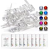
- Overview: 5 mm LED Lamp Diode Light Assortment Kit DC (20mA), Round Lens (Clear Transparent) 2 Leads, 10 colors x 10pcs = 100pcs Mixed Leddiode, Multi Luminous Intensity
- Shipping Weight: 1.54oz / 0.04kg, (Pack of 100) (10 Colors, Each Color 10pcs / Through Hole DIP 2pins 5mmled LEDs Set)
- Compatible with: Indicator Lights, DIY PCB Circuit, Arduino, Raspberry Pi, hobby, Science Experiments, Colorful Throwies Project, Breadboard, T1 T-1 Bulb, Bulk 3.2v 3.3v Parts Replacement,Invisible Black Light
- Color/Wave Length: White: 6000K-9000K(7000K 8000K) Red: 620nm-625nm Green: 515nm-520nm Yellow-Green: 570nm-575nm Blue: 455-465nm Yellow: 588-592nm(590nm 591nm) Orange(Amber): 600nm-610nm UV(Violet/Purple): 395nm-400nm Warm White:3000K
- Luminous Intensity(High Brightness): White:12000-14000mcd Red:2000-3000mcd Green:15000-18000mcd Yellow-Green:500-700mcd Blue:7000-8000mcd Yellow:1500-2000mcd Orange:1500-2000mcd Purple:300-400mcd Pink:7000-8000mcd Warm White: 14000-16000mcd
Protected products
IDEC lists indicators with an internal current-limiting resistor and reverse-polarity protection diode (AP1M122-G). Pololu offers a compact 4–75 V, 8 A reverse-voltage protector (product page) and related ideal-diode modules (category). Verify the exact protected terminals, voltage, current, transient, and thermal specifications before relying on any commercial assembly.
Independent reader supportYour contribution helps us test, update, and keep practical guides available for everyone.How to make an LED show reversed polarity
Anti-parallel LED and diode
Use two opposite-direction branches, each with current limiting:
Input A ──┬── resistor ── LED ──┬── Input B
          └── resistor ── diode ─┘
The LED lights for one polarity and the ordinary diode conducts for the other, protecting the LED from excessive reverse voltage. Use a resistor in each branch (or an equivalent topology that limits both directions), size it for the highest supply voltage, and rate the diode for its forward current and reverse voltage.
Free tools Windows power users keep installed
One-click scans. No signup required.
Two anti-parallel LEDs
Two LEDs can indicate opposite polarities, but each LED must be protected from the other LED’s reverse voltage. This is not automatically safe at arbitrary supply voltage.
Best Value

- Lamp Diameter: 5 mm Round
- Forward Voltage: R/Y 2.0-2.2V; B/G/W 3.0-3.2V
- Max Current: 20 mA
- Emitting Color:White/Red/Yellow/Green/Blue
- Polarity : Anode (Longer Part) /Cathode (Shorter Part)
Comparator or microcontroller
For a reliable logic-level warning over a wide supply range, sense the protected or raw input with a comparator, ADC, or monitoring circuit. Brightness alone is a poor diagnostic when voltage varies.
Testing a suspected backward or damaged LED
- Disconnect power and inspect lead orientation, the package flat, PCB markings, connector wiring, solder bridges, and lifted pads.
- Set a multimeter to diode-test mode.
- Touch the positive probe to the anode and negative probe to the cathode. A forward-voltage reading and faint glow are common.
- Reverse the probes. A healthy discrete LED normally reads open or much higher.
- If readings are ambiguous, remove one lead or test the LED out of circuit.
A meter may not supply enough voltage or current to visibly light some LEDs. A low reading both ways can indicate a short; an open reading both ways can indicate damage, incorrect setup, or an LED package containing electronics. Never connect an unknown LED directly to a bench supply without current limiting.
Special cases
AC supplies
A standard LED should not be connected directly to AC unless its reverse voltage is limited. Use an anti-parallel diode, bridge, an AC-rated indicator, or a properly designed driver. Calculate from the AC peak voltage, not only the RMS label.
Addressable LEDs
Addressable packages contain a control IC and data pins, so reversed power can damage more than the LED die. Protect the module’s power input according to its datasheet. Kingbright advertises reverse-connection protection for one integrated RGB product, but its exact voltage and protected-pin conditions still apply (product page).
LED strips
Many constant-voltage strips include series resistors but not reverse-polarity protection. Follow the strip’s connector markings and documentation.
Automotive lighting
A nominal 12 V automotive system also has cranking undervoltage, load-dump transients, inductive spikes, and wiring disturbances. Battery-reversal protection is only one part of the design. Automotive reference architectures from onsemi (rear lighting, front lighting) and TI (reference design) show protection integrated with driver and transient functions.
Quick Recap
Selection checklist
- Confirm anode and cathode from the exact datasheet or board documentation.
- Use a resistor or constant-current driver for forward operation.
- Check the LED’s specified reverse voltage and reverse-current limit; never assume 5 V.
- Calculate using worst-case supply voltage and verify resistor and protection-device power.
- For a shunt diode, add a fuse or defined current limiter.
- For a MOSFET, verify source/drain orientation, body-diode direction, gate-source limits, and thermal performance.
- Account for diode drops on low-voltage rails and for automotive or inductive transients where applicable.
- Commission the circuit with a current-limited supply and test both correct and reversed connections.
Product prices and availability are accurate as of the date/time indicated and are subject to change. Any price and availability information displayed on Amazon at the time of purchase will apply.
What’s actually slowing this PC down?
Pick the symptom - the matching free tool is one click away.

