
Do these 3 things before closing this tab:
1Scan for outdated or missing drivers - takes under a minute2Repair Windows errors before they cause bigger problems3Fix the driver behind crashes, sound loss and screen glitchesiTechGuides is reader-supported. When you buy through links on our site, we may earn an affiliate commission. As an Amazon Associate I earn from qualifying purchases. Learn more
To make an Arduino change text on a 16×2 LCD as you turn a potentiometer, connect the potentiometer’s wiper to analog input A0, read it with analogRead(A0), and choose a message based on the reading. The example sketch below follows the pin assignments and five text ranges in the Arduino Project Hub project, while correcting its wiring mistake: the A0 potentiometer’s wiper must go to A0, not ground. A separate potentiometer can adjust LCD contrast through pin VO.
What the project does
The Arduino Project Hub project, published June 5, 2022, is intended to display a label and a potentiometer reading on a 16-column, 2-row character LCD. Its sketch reads A0, selects one of five ranges, prints “DIY Inventor” on the first row, prints the matching range label on the second, and writes the numeric reading at column 13. It also sends readings to the Serial Monitor at 9600 baud. The published code and wiring description are not fully aligned, so follow the corrected connections below rather than copying the project’s wiper-to-ground instruction.
The project specifies an Arduino Uno Rev3, a parallel 16×2 LCD, a rotary potentiometer, breadboard, jumper wires, and the LiquidCrystal library. The library is intended for HD44780-compatible displays; an I2C LCD uses a different interface and generally needs a different wiring arrangement. Arduino’s LCD tutorial describes the parallel interface and its control, data, contrast, power, and backlight connections.
Wire the two potentiometer functions correctly
Potentiometer for changing the displayed text
Connect the potentiometer’s two outer terminals across the board’s appropriate supply and ground, and connect its center terminal (the wiper) to A0. Turning the shaft changes the voltage at A0, which the sketch reads as an analog value. The project page’s written direction to connect the wiper/output to Arduino GND conflicts with its use of analogRead(A0); do not follow that direction.
#1 Best Overall

- TURN CODE INTO REAL-WORLD RESULTS — Follow 22+ guided lessons to make LEDs blink, read temperature and distance, move servo and stepper motors, control an LCD and respond to joystick or IR input; ideal for a family weekend build, homeschool unit, coding club or STEM classroom
- MORE PROJECT VARIETY IN ONE ORGANIZED KIT — Includes the UNO R3 controller, LCD1602 with pre-soldered header, breadboard power module, ultrasonic and DHT11 sensors, joystick, IR receiver and remote, SG90 servo, stepper motor, relay, DC motor, fan blade, displays, LEDs, buttons, resistors and jumper wires
- START WITHOUT SOLDERING — Plug-in modules, a solderless breadboard and the pre-soldered LCD help beginners focus on wiring, code and testing; the illustrated component list makes it easier to find each part and move from one lesson to the next
- LEARN THE LOGIC, THEN CREATE YOUR OWN — Use Arduino IDE and the included example code to understand digital input and output, analog sensing, timing, motor control and display functions, then change thresholds, speeds and sequences for alarms, environmental monitors, reaction games and motion projects
- CLEAR SETUP SUPPORT FOR FIRST-TIME BUILDERS — Download the latest tutorial and code, select the UNO board and correct computer port, check component polarity and breadboard rows, and keep power-module input at 9V or below; younger learners should work with an experienced adult
Separate control for LCD contrast
The contrast control has a different job: connect its two outer terminals to +5V and GND and its wiper to LCD VO (pin 3). Arduino’s tutorial documents a 10 kΩ potentiometer for this purpose, while the official library example allows 10 kΩ or 100 kΩ. The project page’s suggestion to tie VO directly to ground is not the adjustable-contrast arrangement documented by Arduino. If you want both changing text and adjustable contrast, use two controls or a verified circuit designed to provide both functions.
LCD and Arduino pin connections
The project sketch uses LiquidCrystal lcd(11, 10, 5, 4, 3, 2): RS to Arduino digital 11, Enable to 10, then LCD D4–D7 to digital 5, 4, 3, and 2. Connect LCD R/W to ground, VSS to ground, and VCC to 5V. Connect the backlight according to the specific module’s pinout and resistor requirements. Arduino’s tutorial example uses a 220 Ω resistor for LED+ to 5V and LED− to ground; the project’s listed 1 kΩ resistor is not a universal substitute, because modules can differ.
Rank #2

- 35+ Guided Electronics Projects: Progress from LEDs and buttons to RFID access, real-time clocks, motion and distance sensing, environmental monitoring, motor control and interactive displays for STEM learning, coding clubs and maker projects
- More I/O and Memory for Larger Builds: The MEGA 2560 R3 provides 54 digital I/O pins, including 15 PWM outputs, 16 analog inputs, 4 hardware serial ports and 256 KB flash for projects that combine more sensors, controls and displays
- 200+ Components for Prototyping: Includes LCD1602, RC522 RFID, RTC, DHT11, HC-SR501 PIR, ultrasonic and water-level sensors, GY-521, MAX7219, keypad, joystick, rotary encoder, relay, SG90 servo, stepper motor, DC motor, breadboard and more
- Learn, Modify and Create: Follow 35+ guided lessons with example code, then adjust sensor thresholds, timing, display text, motor behavior and control logic to turn structured exercises into access systems, monitors, alarms and interactive projects
- Organized for Repeatable Learning: Pre-soldered modules, a solderless breadboard, storage case and small-parts box reduce setup time and keep sensors, LEDs, ICs, wires and other components easy to find between projects
Pin assignments are not interchangeable by guesswork: the physical wiring must match the six numbers passed to the LiquidCrystal constructor. Arduino’s own example uses RS 12 and Enable 11, rather than the project’s 11 and 10. If you use Arduino’s example wiring, change the constructor to LiquidCrystal lcd(12, 11, 5, 4, 3, 2). In either arrangement, lcd.begin(16, 2) sets the display dimensions.
Recommended Free Tools
Choose four-bit or eight-bit LCD mode
The documented project uses four-bit parallel mode, which transfers data using D4–D7. Arduino’s tutorial says four-bit operation uses seven Arduino I/O pins and eight-bit operation uses eleven; it notes that four-bit mode is sufficient for most text-display tasks. Four-bit mode therefore saves pins and is a practical choice for this project. The official LiquidCrystal library repository describes support for HD44780 or compatible displays.
Rank #3

- This is an upgraded Super Starter Kit with free PDF tutorial(23 lessons), developed specially for those beginners who are interested in.
- The kit has 44pcs components With tutorial in a CD including project introduction and source code, add More modules: LED Thermistor Touch sensor module than old version.
- 1602 LCD display with pin header (need to be soldered by yourself)HC-SR04 Ultrasonic 5V Relay Power Supply Module Servo Motor with DC Prototype Expansion Board are included.
- A complete set of most common and useful electronic components for clear listing in a nice Plastic package.
- Detailed tutorials including project introduction and source code CAN BE PROVIDED FOR FREE, contact us BY Email to get documents.
Sketch: select a label from the A0 reading
This version keeps the project’s pin map and range labels, initializes the LCD once, and writes the selected text and reading. The original project’s last range ends at 1000, but the sketch below uses an inclusive fallback for readings above 1000 so the second row is not left without a range label. Its actual behavior still depends on the board’s analog-read resolution and configuration; check the board documentation rather than assuming all Arduino boards return the same range.
#include <LiquidCrystal.h>

LiquidCrystal lcd(11, 10, 5, 4, 3, 2);

void setup() {
  lcd.begin(16, 2);
  Serial.begin(9600);
  lcd.print("DIY Inventor");
}

void loop() {
  int value = analogRead(A0);
  const char *label;

  if (value <= 200) {
    label = "Very Low";
  } else if (value <= 400) {
    label = "Low";
  } else if (value <= 600) {
    label = "Medium";
  } else if (value <= 800) {
    label = "High";
  } else {
    label = "Very High";
  }

  lcd.setCursor(0, 0);
  lcd.print("DIY Inventor    ");
  lcd.setCursor(0, 1);
  lcd.print("                ");
  lcd.setCursor(0, 1);
  lcd.print(label);
  lcd.setCursor(13, 1);
  lcd.print(value);

  Serial.println(value);
  delay(100);
}
Clearing the second row before printing prevents characters from a longer previous label or value remaining visible after a shorter one. A 16-character row is narrow: the label and a multi-digit value can compete for space, and a value longer than three digits beginning at column 13 will be clipped. Adjust the cursor positions or shorten the label if you want more room for the number.
Rank #4
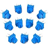
- Package content: you will receive 12 pieces of trim potentiometers with knobs in blue color, suitable for breadboarding and prototyping; Such a sufficient quantity can easily meet your daily usage and replacement demand
- Reliable to use: composed of quality material, these breadboard trim potentiometers are safe and sturdy, reliable and stable, will not easily break or deform, which can be applied for long-term use
- Reasonable design: with round pins rather than flat blade pins of other trimpots, these linear potentiometers are suitable for both breadboarding and PCB; The knurled knob with arrow design allows you to easily adjust by hand or small flat blade screwdriver
- Specification: these trim potentiometers adopt linear resistance change mode, the rotation angle is 270 degrees, and adjustable range is 0-10K ohm, which are easy to connect and can work well
- Dimension information: each rotary potentiometer measure approx. 0.375 x 0.375 x 0.19 inch/ 9.5 x 9.5 x 4.9 mm, such a small size only requires little space, which makes them easy for you to store
The Project Hub version prints a startup message and calls lcd.begin(16, 2) twice. Only one initialization is needed. It defines ranges 0–200, 201–400, 401–600, 601–800, and 801–1000; because the final upper bound is 1000, values above that are not assigned a label by those exact conditions. The sketch here preserves the five thresholds but lets the last range include any higher reading.
Crashes, No Sound, or Screen Glitches?
Random freezes, missing sound and display glitches usually trace back to one bad driver. Find and replace yours safely.Free scan · under a minuteWindows Errors? Fix Them Before They Spread
Repair common Windows errors and clear accumulated junk for a smoother, more stable PC - no reinstall needed.Free scan · no reinstallCheck the interface and displayed output
- Confirm the LCD type. Use a 16×2 parallel HD44780-compatible module for the LiquidCrystal wiring shown. If the module is an I2C variant, identify its interface and use an appropriate library and wiring rather than connecting it as a parallel LCD.
- Check the pin map. Verify RS, Enable, D4–D7, power, ground, VO, and backlight against both the module labels and the constructor in the sketch.
- Upload and observe the display. The first row should show “DIY Inventor”; turning the A0 potentiometer should change the second-row range label and reading.
- Use Serial Monitor if needed. Set it to 9600 baud to see the numeric A0 readings being printed by the sketch.
If the backlight turns on but no characters are visible, check the contrast connection at VO and adjust its potentiometer. If the text does not respond to the control, check that the analog potentiometer’s center terminal really reaches A0 and that its outer terminals connect to supply and ground. If characters are garbled or missing, recheck the LCD pin order and constructor; the documented example is for a parallel display, not an I2C module.
Quick Recap
Best Value

- This electronic sensor kit contains 48 pieces most popular and mainstream sensors and modules, allow you to do a lot of devices, robots and other interactive projects. This kit Not contains arduino controller board.
- Compatible with various micro-controllers and Raspberry Pi, such as mega 2560, r3 development board, pro micro, leonardo, etc. Note we only offer arduino instructions.
- We provide detailed projects for each sensor based on development board, including wiring method, test code, etc. Download the arduino tutorial from the wiki website.
- This is complete sensor kit with exquisite packaging. It's a good electronics kit for junior high and high school inventors, hackers, designers, and tinkerers of all levels.
- The tutorials show wiring for the Arduino and give example codes. All of this makes getting started with sensors quite easy. The professional team is ready to answer any questions.
What to check when choosing parts
- Confirm the LCD is a 16×2 HD44780-compatible parallel module if you plan to use the wiring and library shown here.
- Check whether a starter kit includes a compatible LCD, its pinout, breadboard, jumper wires, and suitable backlight resistor; kit contents vary.
- Plan for the analog-control potentiometer and a separate contrast potentiometer if you want both input control and adjustable character contrast.
- Follow the specifications of your particular LCD for backlight wiring and resistance instead of assuming a resistor value applies to every module.
Product prices and availability are accurate as of the date/time indicated and are subject to change. Any price and availability information displayed on Amazon at the time of purchase will apply.

