
iTechGuides is reader-supported. When you buy through links on our site, we may earn an affiliate commission. As an Amazon Associate I earn from qualifying purchases. Learn more
The gauge face alone is not enough to specify a matching oil-pressure transmitter. It can usually tell you the pressure scale, units and sometimes the pressure reference or accuracy class. To order a transmitter that fits and measures correctly, also identify the connection, oil compatibility, temperature and pressure limits, electrical output, power and wiring. Match the measurement and installation—not merely the gauge’s maximum reading or brand.
What can you learn from the gauge face?
Start by recording the markings on the dial. They are useful for identifying the measurement, but do not treat them as a complete purchase specification.
- Scale and units: for example, 0–100 psi, or a dual psi/bar scale.
- Pressure reference: gauge, vacuum or compound markings, if shown. An ordinary oil-pressure gauge commonly measures gauge pressure, but confirm from the machine documentation.
- Accuracy class: sometimes printed on the dial.
- Manufacturer, model and special markings: note any series, part number, liquid-fill indication, or approval markings.
- Physical dial size: measure it if you need to preserve the same local display size; it does not determine transmitter range.
A typical mechanical dial does not establish the thread standard, seal method, wetted materials, temperature limit, overpressure rating, electrical output or supply voltage. Photograph the dial and the rear or lower connection, and look for a nameplate. Use the exact model and suffix to find the manufacturer’s datasheet; similar-looking models can have different connections, materials or ratings. Also check the machine’s OEM parts list for adapters, snubbers or unusual fittings.
Confirm what pressure the instrument must measure
Pressure reference
Gauge pressure is measured relative to atmospheric pressure and is common for engine, hydraulic, compressor and lubrication systems. Absolute pressure is referenced to a perfect vacuum. Vacuum pressure describes pressure below atmospheric pressure; a compound range includes both vacuum and positive pressure. Differential pressure measures the difference between two ports. These are distinct configurations, not interchangeable labels. A transmitter with the wrong reference may produce a steady, plausible-looking but incorrect reading. Check the equipment documentation or old instrument markings before specifying it. WIKA’s pressure-sensor overview lists these configuration types.
#1 Best Overall

- Exquisite design: Oil Pressure Tester Tool have dual display pressure gauge head, clear scale, easy to clean, and equipped with rubber buffer protection cover, shockproof and scratchproof.
- Complete accessories: Oil Pressure Tester select high-quality metal materials, 10 adapters to fit most brands and models, suitable for most gasoline and small diesel engine cars, motorcycles, boats and other vehicles, as long as the adapter can match your engine and The oil pressure does not exceed 140PSI, each marked with a number, stored in a fixed position in the red case for easy selection.
- Oil-resistant hose: Oil Pressure Tester Oil-resistant and high-temperature resistant hose, freely bendable, sturdy and durable, giving you professional high-quality products.
- Brass Fittings: Oil Pressure Gauge kit brass straight elbow quick fittings, quick and easy to install, faster, simpler, more reliable sealing, two types of straight and curved, to meet more needs. Durable, safe and environmentally friendly.
- 100% Satisfaction: We Oil Pressure Gauge kit are responsible for every product. If you have any problems with our products or services, please contact us immediately and we will provide you with exceptional responses to your every
Range, normal pressure and transients
Write down three values separately: the gauge’s printed scale, the normal operating band and the highest credible transient or fault pressure. Transients can occur at startup, when a line is blocked, at pump deadhead, from thermal expansion or around relief-valve operation.
Choose a calibrated range that includes normal operation while leaving adequate resolution and accuracy. A very wide range can make the normal operating pressure occupy too little of the signal; a range that is too narrow can be exceeded during routine spikes. Check the selected transmitter’s proof-pressure or overpressure rating separately: these ratings are not the same as its continuous measuring range.
WIKA describes a range approximately twice the optimal operating pressure as a general pressure-gauge selection rule of thumb, not a universal transmitter rule. Use the actual operating and transient conditions and the transmitter datasheet to make the decision. See WIKA’s gauge-selection guidance and transmitter-selection guidance.
Example: A 0–100 psi gauge used normally at 45–60 psi, with an occasional 120 psi spike, does not automatically call for a 0–100 psi transmitter. A 0–100 or 0–150 psi calibrated range might be appropriate depending on accuracy and the verified transient; the device must also withstand the transient within its specified rating. A 0–500 psi range may tolerate the pressure but could sacrifice useful resolution or accuracy in the normal operating band.
Identify the connection before ordering
Connection mismatches are a frequent reason a seemingly suitable transmitter will not install. Record each of the following from the instrument, machine drawing or a correctly identified fitting:
Rank #2

- Exquisite design: Oil Pressure Tester Tool have dual display pressure gauge head, clear scale, easy to clean, and equipped with rubber buffer protection cover, shockproof and scratchproof.
- Complete accessories: Oil Pressure Tester select high-quality metal materials, 10 adapters to fit most brands and models, suitable for most gasoline and small diesel engine cars, motorcycles, boats and other vehicles, as long as the adapter can match your engine and The oil pressure does not exceed 140PSI, each marked with a number, stored in a fixed position in the red case for easy selection.
- Oil-resistant hose: Oil Pressure Tester Oil-resistant and high-temperature resistant hose, freely bendable, sturdy and durable, giving you professional high-quality products.
- Brass Fittings: Oil Pressure Gauge kit brass straight elbow quick fittings, quick and easy to install, faster, simpler, more reliable sealing, two types of straight and curved, to meet more needs. Durable, safe and environmentally friendly.
- 100% Satisfaction: We Oil Pressure Gauge kit are responsible for every product. If you have any problems with our products or services, please contact us immediately and we will provide you with exceptional responses to your every
- Thread standard, such as NPT, BSPP/G, BSPT/R, metric, SAE or UNF.
- Nominal size, such as ¼ inch or M14.
- Male or female, and straight or tapered thread.
- Connection location and mounting: bottom, rear, side or remote.
- Sealing method: thread sealant, O-ring, bonded washer, cone seat, face seal or gasket.
- Pressure-port shape and insertion depth, plus any adapter, snubber, restrictor, valve or diaphragm seal.
NPT is common in the United States, but do not assume it. WIKA treats thread type, size and connection location as separate selection details in its gauge-selection guide.
If the thread is unknown
- Follow the equipment procedure to shut down, isolate, depressurize and drain the line.
- Photograph the installed connection before removing the gauge.
- Measure the outside diameter of a male thread or the inside diameter of a female thread, and measure pitch with a thread-pitch gauge.
- Check whether the thread is tapered and inspect for an O-ring groove, shoulder, cone or washer seat.
- Compare measurements with manufacturer thread drawings or ask an instrumentation supplier or machinist to identify it.
Do not force a metric or BSP fitting into an NPT port, or rely on thread tape to compensate for a mismatched thread or sealing face. An adapter is appropriate only when its thread, seal, pressure and temperature ratings, material and installation geometry suit the service.
Recommended Free Tools
Check oil compatibility, temperature and pressure-element design
Specify the actual oil and service conditions, not just “oil.” Engine, hydraulic, gear, compressor and process oils can differ in additives, viscosity, contaminants and temperature. Check every wetted component: pressure port, diaphragm, weld, seal or O-ring, any internal fill fluid, and any seal or adapter in the assembly. Stainless steel is not a blanket compatibility guarantee; compatibility depends on the oil formulation, temperature, pressure and exposure.
Common material options include stainless-steel grades, copper alloys, nickel alloys and seal materials such as FKM/FPM, EPDM, NBR or PTFE. The manufacturer’s datasheet must confirm the exact configured materials for the chosen transmitter. For example, Ashcroft’s GC51 page specifies a 17-4PH stainless-steel diaphragm and 316 stainless-steel process connection; these are model-specific details, not proof of compatibility with every oil. Ashcroft’s E2G page describes a configurable model with material options.
Record normal and maximum oil temperature as well as ambient temperature at the transmitter. Check the device’s temperature limits and temperature-related measurement error. If oil is highly viscous, contaminated, prone to polymerizing, or likely to clog a small port, ask about a flush diaphragm or a suitably specified diaphragm seal. WIKA identifies flush-diaphragm options for viscous or clogging media in its sensor-selection guidance.
Rank #3
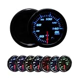
- FUNCTION: This 0-140 PSI Oil Pressure Gauge is Designed to Monitor and Display the Pressure Running Through the Fuel System of Your Car or Truck
- DESCRIPTION: Oil Pressure Readings from 0 to 140 PSI - 2-1/16 inch (52mm) Gauge with Black Dial, Tinted Lens and Illuminated Red Needle
- Chroma Cycle: Connect the red wire to the car ignition source - 7 solid color modes and 2 color cycling modes allow you to match the factory dashboard lights or add custom styles to the interior of the vehicle - colors include blue, red, green, cyan, purple, white, and yellow
- PACKAGE INCLUDES: 1 Oil press gauge, 1 Oil Press Sensor, 1 Power Harness, 1 instruction paper, 1 U Holder, and some hardwares
- ELECTRONIC SENSOR INCLUDED: Comes with an Electronic Oil Pressure Sensor that provides pinpoint precision readings to ensure your bearings, crankshaft and other critical engine parts stay properly lubricated
Choose an output that the controller can accept
A normal mechanical gauge has no electrical signal for a PLC or data logger. Exceptions include gauges with switch contacts, potentiometric or inductive outputs, mechatronic designs, or an integrated transmitter. Check the existing instrument before assuming it is purely mechanical.
Free tools Windows power users keep installed
One-click scans. No signup required.
4–20 mA
4–20 mA is a common industrial-control choice because it is generally more tolerant of cable voltage drop and electrical noise than a voltage signal. It is not automatically right for every controller: verify that the receiving input supports it. For a transmitter configured linearly from a low pressure Plow to a high pressure Phigh:
I = 4 mA + 16 mA × (P − Plow) / (Phigh − Plow)
For a 0–100 psi range, 0 psi corresponds to 4 mA, 50 psi to 12 mA and 100 psi to 20 mA. At 60 psi the expected signal is 13.6 mA. Confirm the configured range and direction: transmitters can use reverse ranges such as 20–4 mA or other scaling.
Voltage, digital and switch outputs
Outputs such as 0–10 V or 1–5 V suit equipment designed for the particular voltage input; they are not interchangeable with a 4–20 mA input. HART, IO-Link, CAN and fieldbus options require compatible receiving hardware. HART-equipped transmitters often retain 4–20 mA as the primary analog signal, but verify the specific model and configuration. A pressure switch may be enough for a simple high- or low-pressure alarm, shutdown or pump control; choose a transmitter when continuous data, trending or proportional control is required. WIKA lists analog and digital variants in its sensor overview, and its DPT-20 page lists particular HART and fieldbus variants.
Rank #4

- GlowShift Tinted 7 Color Series Oil Pressure Gauge is Designed to Monitor & Display the Amount of Oil Pressure Running Through Your Car or Truck's Engine
- Oil Pressure Readings from 0 to 100 PSI - 2-1/16" (52mm) Diameter Gauge with a Black Dial, Illuminated Red Needle, Tinted Lens, Matte Black Trim Ring & Aluminum Housing
- 7 Solid Color Modes & 2 Color Cycle Modes Allow You to Match Your Factory Dashboard Lights or Add a Custom Style to the Interior of Your Vehicle - Colors Include Blue, Red, Green, Teal, Purple, White & Yellow - Connecting the Dimmer Wire to the Headlight Switch Reduces Brightness of the Gauge by 30% When the Headlights are On
- Includes 1/8-27 NPT Pressure Sensor, 9' Sensor Harness, 2' Power Harness, Gauge Visor, Mounting Bracket, Mounting Bracket Hardware & Step-By-Step Instructions that Help Walk You Through the Installation Process
- Established Since 2004, GlowShift Has Always Been Committed to Customer Satisfaction by Offering a One-Year Limited Warranty, Free Lifetime Technical Support & 30 Day No Hassle Returns with Each Purchase
Verify power, wiring, accuracy and protection
For a two-wire loop-powered transmitter, check supply-voltage range, polarity and maximum loop resistance. The transmitter, cable resistance, PLC input, isolator, barrier and power supply must fit within the manufacturer’s loop-load limits. Also confirm whether the installation needs two-, three- or four-wire wiring, the connector or cable termination, and an intrinsic-safety barrier. Do not wire by analogy with another model; terminal labels and polarity vary, so use the selected transmitter’s manual.
Compare accuracy specifications carefully. A mechanical gauge may state an accuracy class; a transmitter may state reference accuracy, terminal-point accuracy, total error band or percentage of span. For a 0–100 psi span, ±0.25% of span is ±0.25 psi, not ±0.25% of whatever pressure happens to be measured. Check temperature effect, stability, hysteresis, repeatability, supply effect and calibration uncertainty as relevant to the application. For a specific model, rely on its configured datasheet; Ashcroft publishes model- and range-specific accuracy details for the GC51.
Specify enclosure protection such as IP or NEMA rating, EMC requirements and any hazardous-area or functional-safety approvals required at the installation. A marking on the old gauge does not establish that a new transmitter has the same approval.
Choose an installation arrangement
| Arrangement | Useful when | Trade-offs |
|---|---|---|
| Standalone transmitter replacing the gauge | The old connection and pressure specification are known, remote output is the priority, and the transmitter fits the space. | May not preserve local indication; body clearance, vibration and temperature can differ from the old gauge. |
| Existing gauge plus separate transmitter | Local visual indication must remain and a suitable second pressure tapping point is available. | Adds potential leak points and the two instruments may not read identically; a manifold or tubing may be needed. |
| Integrated gauge-transmitter | Local indication and an electrical signal are both wanted in one assembly. | Can be compact, but a failure may remove both functions and replacement may be model-specific. Ashcroft’s T5500E is one example. |
| Pressure switch | Only a discrete alarm, shutdown or on/off control is needed. | Does not provide continuous pressure measurement for trending or proportional control. |
Do not assume the old gauge must be discarded: if reliable local indication is needed, retaining it while adding a transmitter can be preferable. Conversely, an integrated instrument is not automatically the best choice simply because it reduces fittings.
What’s actually slowing this PC down?
Pick the symptom - the matching free tool is one click away.
Use this identification worksheet
| Item | Record | Example |
|---|---|---|
| Media | Oil name/type and known additives or contaminants | Engine lubricating oil |
| Pressure reference | Gauge, absolute, vacuum, compound or differential | Gauge |
| Gauge scale and units | Lowest and highest marked values; required units | 0–100 psi |
| Operating and maximum pressure | Normal band and verified spike, relief or deadhead pressure | 45–60 psi; 120 psi spike |
| Existing instrument | Type, dial diameter, maker, model, serial and connection code | Record from nameplate and measurement |
| Process connection | Standard, size, gender, seal, location and any adapter | ¼ NPT male, bottom mount (only if verified) |
| Materials and temperature | Required wetted materials and oil/ambient temperature ranges | Oil-compatible materials; record actual limits |
| Electrical interface | Output, supply, wiring, input type and loop-load limits | 4–20 mA, 24 VDC, two-wire (if compatible) |
| Performance and environment | Accuracy, response/damping, enclosure rating and approvals | Specify from process and site requirements |
| Documentation | Drawings, manuals, certificates and photographs | Gauge face, connection and machine port |
Install and commission the transmitter safely
- Isolate, depressurize and drain the process under the equipment procedure. Confirm the port and fitting are suitable before installation.
- Verify thread, sealing face, materials, pressure rating and temperature rating. Use only a correctly specified, pressure-rated adapter if required.
- Install according to the transmitter and machine instructions. Consider pulsation, vibration, mounting orientation, clearance and any snubber or seal; do not assume a liquid-filled gauge means the transmitter needs the same damping.
- Restore pressure carefully and inspect the connection for leakage using the approved site method.
- Wire the transmitter to the correct input using its manual. Confirm supply voltage, polarity, loop resistance and any barrier or isolator.
- Apply known pressure with a calibrated reference or suitable pressure source. Measure loop current, check zero and span, and verify the controller’s engineering-unit scaling at multiple points.
- Compare readings against a calibrated reference rather than treating the old gauge as a calibration standard. Document the range, units, wiring, configuration and reference used.
Oil-system pulsation and machine vibration can cause unstable readings or shorten service life. A snubber, restrictor, damped transmitter, suitable impulse line, diaphragm seal or software damping may help, but each affects response and must suit the pressure and process. A liquid-filled gauge is intended to cope with vibration or pulsation in some installations; that does not determine the transmitter’s response configuration. See the WIKA 432.30/433.30 gauge information for an example of liquid-filled gauge options.
Best Value

- High Night Visibility: Equipped with a bright white LED light for clear visibility in all lighting conditions, ensuring safe driving at night.
- Wide Monitoring Range: Precisely monitors oil pressure from 0-100 PSI.
- Precise LED Display: Provides accurate readings and alerts drivers to critical operating conditions, making it easy to install and replace.
- Complete Kit Included: Comes with the instrument, sensor, harness, and instructions. No additional sensors required, ensuring a perfect fit.
- Universal Compatibility: Powered by 12V DC with a 2" (52mm) diameter, suitable for cars, SUVs, trucks, and other vehicles.
Worked example and purchasing request
Suppose the old gauge is marked 0–100 psi, normal oil pressure is 45–60 psi, and the machine documentation confirms a 120 psi maximum transient. If inspection verifies a ¼ NPT male connection, a preliminary request might specify gauge pressure, a 0–100 or 0–150 psi calibrated range to be confirmed against accuracy needs, verified transient tolerance, compatible wetted materials and seals, 4–20 mA, and a supply and wiring arrangement compatible with the controller. The proof/overpressure rating, temperatures and exact connection must still be checked against the transmitter datasheet and machine requirements; the example values are not a universal selection.
Copy and complete this request for quotation:
Please quote a pressure transmitter for oil service:
- Media and oil type: [ ]
- Pressure reference: [gauge/absolute/differential/other]
- Measuring range and units: [ ]
- Normal operating pressure and maximum transient: [ ]
- Process connection, size, gender and seal: [ ]
- Mounting and required port geometry: [ ]
- Wetted materials and seal material: [ ]
- Oil and ambient temperature ranges: [ ]
- Output and configured scaling: [ ]
- Supply voltage, wiring and controller input: [ ]
- Accuracy and response/damping requirement: [ ]
- Electrical termination and enclosure rating: [ ]
- Hazardous-area or other approvals: [ ]
- Required certificates: [ ]
- Existing gauge model, machine model and photographs: [ ]
For packaged engines, compressors, generators or hydraulic units, check the OEM parts list first: a direct-fit replacement may use a nonstandard connector or signal scaling. Otherwise, provide the completed specification and gauge/port photographs to an instrumentation supplier or the manufacturer’s configurator. Exact ranges, materials, outputs and ratings depend on the configured part number.
Windows Errors? Fix Them Before They Spread
Repair common Windows errors and clear accumulated junk for a smoother, more stable PC - no reinstall needed.Free scan · no reinstallCrashes, No Sound, or Screen Glitches?
Random freezes, missing sound and display glitches usually trace back to one bad driver. Find and replace yours safely.Free scan · under a minuteTroubleshoot a mismatch after installation
Output is wrong even though the gauge reads normally
Check whether the transmitter is gauge or absolute, confirm its configured range and output direction, and verify PLC scaling and units. Apply known pressure, measure current with a suitable calibrated meter, and check for a blocked port, valve, adapter or snubber. A mechanical gauge reading normally does not prove the transmitter or PLC is calibrated.
The transmitter does not fit or leaks
Stop rather than forcing it. Recheck thread standard, size, gender, taper and sealing face. Use a suitable adapter only after verifying its pressure and temperature rating, material and geometry; the preferred fix is usually to order the correct transmitter connection.
The two instruments disagree
Possible causes include each instrument’s accuracy and calibration, temperature, pulsation, response time, different measurement locations, or mechanical gauge friction or damage. Compare both against a calibrated pressure reference before adjusting either instrument.
The signal stays near 4 mA or 20 mA
Possible causes include pressure outside the configured range, wiring fault, inadequate supply voltage, sensor fault, incorrect input configuration or model-specific fault-current behavior. Consult that transmitter’s manual for diagnostics and fault-current meaning.
Quick wins for a faster PC:
Scan for outdated or missing drivers - takes under a minuteDriver Scan →Repair Windows errors before they cause bigger problemsFix Now →The pressure port clogs
For viscous or contaminated service, assess a flush diaphragm, correctly specified diaphragm seal, larger port or suitable snubber with the manufacturer. WIKA discusses these media considerations in its sensor-selection guidance; do not fit a small-port device without checking clogging risk.
Quick Recap
Product prices and availability are accurate as of the date/time indicated and are subject to change. Any price and availability information displayed on Amazon at the time of purchase will apply.

