
iTechGuides is reader-supported. When you buy through links on our site, we may earn an affiliate commission. As an Amazon Associate I earn from qualifying purchases. Learn more
To detect loss of signal on an RS-485 bus, monitor differential activity and require it to remain absent for a defined interval. A fail-safe receiver alone is not a loss-of-signal (LOS) detector: it deliberately outputs a known logic level when the pair is idle, open, shorted, or otherwise outside its valid differential range. Use a receiver-based activity circuit for a quiet or disconnected pair, and add a protocol heartbeat or response timeout when you must prove that a remote device is operating.
Fail-safe reception and LOS indication are different
An RS-485 receiver compares the voltage difference between its A and B inputs. Fail-safe behavior prevents the logic output from becoming random when the bus is idle or faulted. It does not prove that valid messages are present.

Analog Devices’ AN-960 describes a conventional receiver as guaranteed high at a differential input of at least +200 mV and guaranteed low at −200 mV or less. Between those limits, the output is not guaranteed. An undriven, open, or shorted pair can settle in that region, depending on termination, bias resistors, cable, and receiver loading. The +200 mV and −200 mV figures describe that conventional example, not a universal guarantee for every modern transceiver.
Do these 3 things before closing this tab:
1Repair Windows errors before they cause bigger problems2Scan for outdated or missing drivers - takes under a minute3Clear out junk files and repair common Windows errorsA receiver specified as fail-safe-high when disconnected, shorted, or not actively driven will produce the same defined high output during a legitimate idle period. Declaring LOS therefore requires a time window, additional logic, or protocol context.
#1 Best Overall

- [ USB TO SERIAL RS-485/422 ADAPTER ] : Compact design with a unique I/O circuit with an internal zero delay. The transceiver controls the data stream automatically without handshaking RTS, DTR, etc. signals.
- [ INDUSTRIAL READY ] : Equipped for 600W surge protection, 15kV ESD isolation, and baud rates from 300bps to 1Mbps. Ready for commercial, industrial, and office applications.
- [ RELIABLE CONNECTIONS ] : USB to RS485 Adapter with built-in signal tester features Power, TX, and RX LED indicators for quick and easy connection testing. Integrated terminal block connector with screws for secure wired RS485 and RS422 conversions.
- [ WIDE COMPATIBILITY ] : Built with an FTDI Chipset. Works seamlessly with Windows 7, 8, 10, 11, Linux, and macOS 10.X, making it a highly versatile solution across platforms.
- [ WHY Gearmo? ] : Your trusted partner based in the USA, providing advanced engineering, highly reliable and superior built products to handle the most demanding industries for over 10 years.
What “loss of signal” should mean in your system
| Requirement | What is actually detected | Suitable method |
|---|---|---|
| Detect a disconnected or quiet pair | No qualifying differential activity for a specified period | Receiver-based activity detector with filtering |
| Detect an open, short, or idle condition | The receiver’s defined response to those physical states | Full-failsafe receiver, with topology and termination verified |
| Know that a particular node is alive | A valid response from that node | Protocol polling, heartbeat, and response timeout |
| Know that valid application traffic is flowing | Correct frames, addresses, and error checks | Protocol parser and supervision logic |
Physical activity from another node cannot establish that the target meter or controller is healthy. For that requirement, combine physical-layer monitoring with an application-level check.
Documented circuit approaches
Receiver comparison followed by time filtering
Analog Devices AN-1451 shows a nonisolated detector using a second ADM3078E transceiver as a bus monitor. The monitor receiver outputs are combined with an NC7S08 AND gate, then passed through a resistor-capacitor low-pass filter before reaching a microcontroller. In the described arrangement, agreement between the receiver outputs corresponds to approximately zero bus differential voltage; the filter prevents a short logic glitch from being reported as a sustained LOS condition.
Receiver propagation-delay mismatch can create brief disagreement even during normal transitions. The application note gives an example RC arrangement for its energy-metering circuit, but its component values are not universal. Select the time constant from the bus’s data rate, legitimate quiet intervals, receiver delays, logic-family behavior, layout, and required alarm latency. Recheck whether the monitor must cross an isolation barrier; the example is nonisolated and may not suit a grounded or isolated product.
What’s actually slowing this PC down?
Pick the symptom - the matching free tool is one click away.
Rank #2

- Bus analysis of ADM3053 isolated version
Full-failsafe receiver
Renesas AN1593 describes using a full-failsafe receiver whose defined response to zero differential voltage is logic high as part of an LOS detector. In that detector arrangement, termination is used so the undriven bus collapses toward zero differential voltage. The LOS indication must still persist long enough to distinguish a real loss from an ordinary idle gap.
Apply this as a design pattern, not as a guarantee for every part. Confirm the selected receiver’s fail-safe thresholds, open- and short-circuit behavior, common-mode range, propagation delay, and output truth table under the actual supply and temperature limits.
Biasing and integrated fail-safe behavior
A pull-up and pull-down bias network can force a defined idle differential voltage. Its resistor values depend on supply voltage, termination resistance, total receiver unit load, cable length, and the number of nodes. Excessive bias increases bus loading and driver current; insufficient bias may not maintain the intended idle margin.
Rank #3

- CAN Mode: Automatic regonize the direction of CAN-H and CAN-L, can read CAN BUS Baud Range: 50, 83, 100,125,150,200,250,300,400,500,666,800,1000kbps
- LIN Mode: can read LIN BUS Baud Range: 2400-4800-9600-14400-19200bps. Red plug connects to LIN, black plug connects to GND.
- PWM Singal Mode: < 20V PWM singal detector for line.
- View Standard Frames ID data: Easy to stop the ID page to read the part of standard frames data.
- Directly use CAN/LIN/PWM analyzer quickly check if the plug with communication data or not.
Some transceivers integrate fail-safe thresholds or biasing. Texas Instruments’ SN65HVD178x-Q1 datasheet, for example, specifies a failsafe-high receiver output when the inputs are disconnected, shorted, or not actively driven. That statement applies to the specified device and conditions; it should not be generalized to other transceivers without checking their current datasheets.
How to choose the detection interval
Measure or calculate the longest legitimate period during which the monitored pair can remain quiet. Include inter-frame gaps, scheduled polling delays, turnaround time between transmitters, startup behavior, retries, and any low-duty-cycle operating mode. Set the LOS threshold longer than that period, with margin for clock tolerance and receiver delay.
- Too short: normal idle gaps and propagation-delay glitches cause false alarms.
- Too long: a real cable failure is reported late.
- No filtering: a single transition or logic hazard can clear or assert the flag unexpectedly.
- No recovery rule: the indication may chatter when traffic resumes.
Use a defined clear policy: clear immediately on qualifying activity only if the system tolerates chatter, or add debounce/hysteresis when the status drives an alarm, reset, or safety response.
Implementation checklist
- Define the claim. Decide whether LOS means no differential transitions, an idle/open/short state, invalid frames, or no response from a named node.
- Characterize the bus. Record termination locations and values, bias resistors, node count and unit loads, cable length, common-mode conditions, data rate, and normal quiet periods.
- Select the receiver behavior. Use the current datasheet for guaranteed high and low thresholds, fail-safe operation, input hysteresis, propagation delay, and fault protection. Do not rely on the conventional ±200 mV figures as a universal specification.
- Choose the monitor location. Determine whether it shares ground with the bus and whether galvanic isolation is required. Place isolation and power-domain boundaries deliberately.
- Generate an activity signal. Compare receiver outputs or use the selected full-failsafe arrangement. Ensure the logic polarity matches the intended idle and LOS states.
- Filter and qualify. Add the RC, digital timer, counter, or debounce logic needed to reject glitches while meeting the alarm-latency requirement.
- Test fault cases. Check normal idle, open cable, shorted pair, missing bias, extra termination, powered-down nodes, common-mode excursions, and traffic resumption.
- Add protocol supervision when needed. Require a valid addressed response or heartbeat if the product must detect a failed remote application rather than merely a quiet physical pair.
Common failure modes
Calling fail-safe high an activity flag
A defined high output during idle is successful fail-safe operation, not evidence of traffic. A separate activity detector or protocol monitor is required.
Using an arbitrary RC value
The filter must be derived from actual receiver delays, bus timing, and acceptable alarm latency. Values from an application note are examples for that circuit, not production defaults.
The Tool Desk
Outbyte Driver Updater FREEScan for outdated or missing drivers - takes under a minuteDriver Scan →Outbyte PC Repair FREERepair Windows errors before they cause bigger problemsFix Now →Ignoring termination and loading
Termination, bias networks, receiver inputs, and cable impedance determine the differential voltage seen when no driver is active. Changing any of them can invalidate the detector’s assumed zero-differential condition.
Best Value
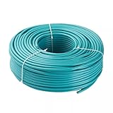
- 1. Profibus DP fast connection standard cable, bus cable radial symmetrical design, allowing the use of stripping tools, can quickly and easily assemble the bus connector. Standard bus cables are specifically designed for assembly.
- 2. Solid bare copper wire conductor, 2 core and synthetic pair, the core line is red and green.
- 3. Aluminum foil, bare metal wire braided double shield, PVC outer sheath.
- 4. Comply with VDE 0472 standard; Class B test (IEC332.1).
- 5. Working parameters: single line transmission specifications: 1000m, plus repeater can be extended to 10000m
Confusing physical silence with node failure
A healthy multidrop network may be silent because no transaction is scheduled. Conversely, another node can create transitions while the device you care about is powered off. Use a heartbeat or addressed response timeout for node-health supervision.
Relevant design references
- Analog Devices AN-1451 documents the receiver-comparison and low-pass-filter approach and states that an LOS detector can alert a microcontroller when a connector or RS-485 cable is disconnected.
- Renesas (formerly Intersil) AN1593 explains exploiting full-failsafe behavior to detect an LOS bus condition. It is an older application note, so pair it with current component data.
- Analog Devices AN-960 explains conventional receiver threshold behavior and the undefined differential-input region.
- Texas Instruments’ 2018 fail-safe-biasing article explains how bias resistors maintain a defined idle logic level; the cited SN65HVD178x-Q1 Rev. C datasheet is dated 2017.
Standards, application notes, and device specifications can change. Verify the current datasheet and the governing RS-485 requirements before releasing a production design.
Quick Recap
Product prices and availability are accurate as of the date/time indicated and are subject to change. Any price and availability information displayed on Amazon at the time of purchase will apply.
Free tools Windows power users keep installed
One-click scans. No signup required.

